Aggregation switch apparatus for broadband subscribers

Inactive Publication Date: 2006-06-22
ELECTRONICS & TELECOMM RES INST
View PDF3 Cites 22 Cited by
  • Summary
  • Abstract
  • Description
  • Claims
  • Application Information

AI Technical Summary

Benefits of technology

[0013] It is, therefore, an object of the present invention to provide an aggregation switch apparatus for broadband subscribers for

Problems solved by technology

A technology of x digital subscriber lines (DSL) using a regular telephone line which is a precedent subscriber network technology and a technology of hybrid fiber coaxial (HFC) using coaxial cables are sufficient to provide bandwidth from 1 to 10 Mbps but still have technical limitations in providing a wide range of bandwidth.
However, these Ethernet switches are specifically designed for LANs and thus, being ineffective in respect of function and performance for processing subscriber traffic.
Especially, there barely exists traffic between subscribers at a subscriber network.
However, currently employed Ethernet switches for configuring subscriber networks based on the traditional Ethernet technology do not fully reflect the above-described subscriber network characteristics.
That is, since the Ethernet switch is specifically designed to be suitable for LANs in which inter-subs

Method used


Image

  • Aggregation switch apparatus for broadband subscribers
  • Aggregation switch apparatus for broadband subscribers
  • Aggregation switch apparatus for broadband subscribers

Examples


first embodiment

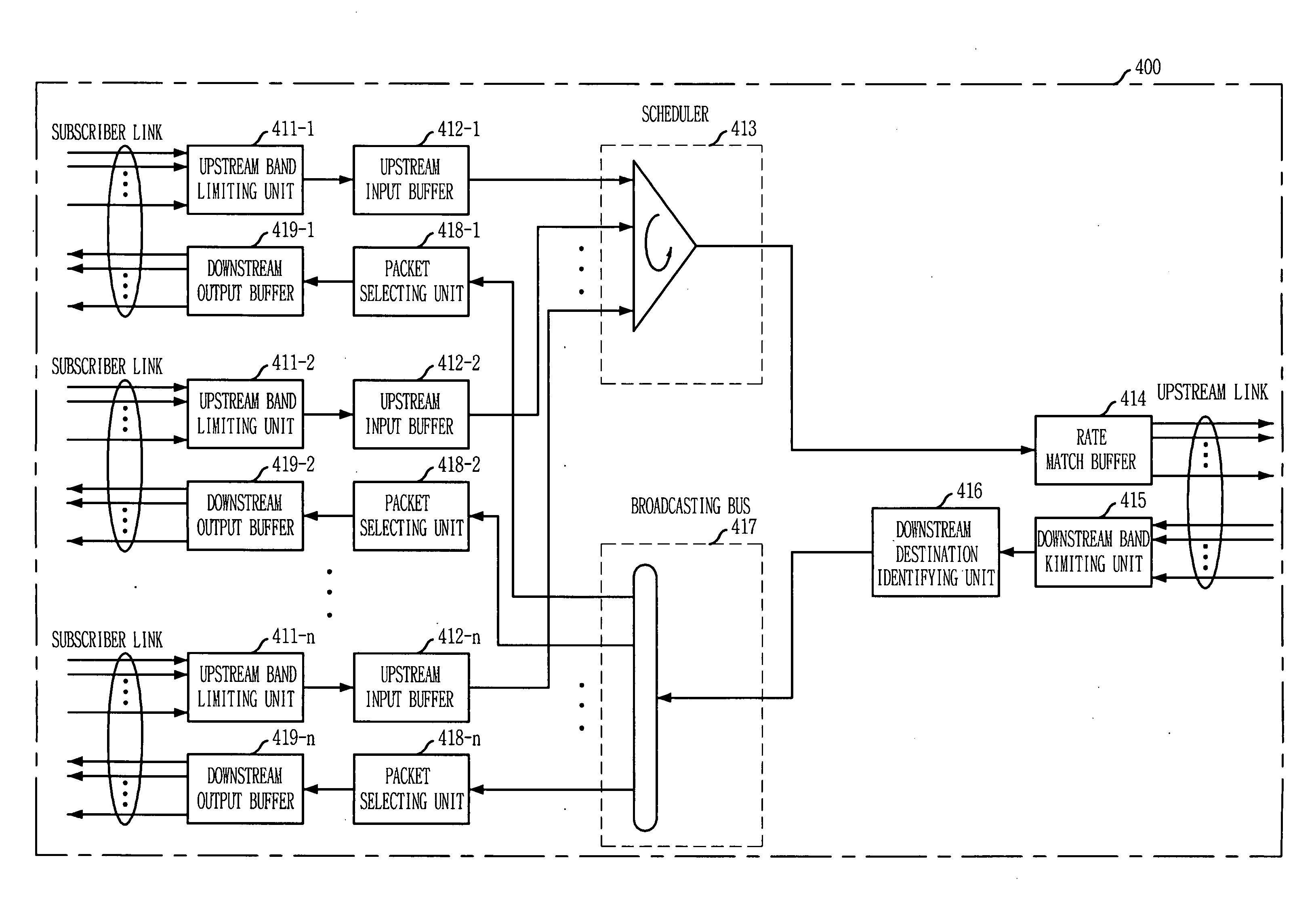
[0063] In the present invention as explained in FIG. 4, when the packets enter to the upstream links, the downstream destination identifying unit 416 determines a destination port of the corresponding packet and attaches this information to the corresponding packet in the form of a tag. Then, the packet selecting units 418-1 to 418-n allocated at the respective terminals of the broadcasting bus 416 pass the packet arrived at the corresponding destination by using this attached tag. Comparing with this configuration, the aggregation switch apparatus 600 in FIG. 6 undergoes a different mode. That is, the packets enter to the upstream links are not subjected to the destination identification procedure but are transferred through the broadcasting bus 416 to the downstream destination identifying units 417-1 to 417-n allocated at the respective terminals of the broadcasting bus 416. Then, the individual downstream destination identifying units 417-1 to 417-n investigate destination Ether...

fifth embodiment

[0070]FIG. 8 is a diagram showing an aggregation switch apparatus for broadband subscribers in accordance with the present invention. The aggregation switch apparatus in FIG. 8 specifically includes an upstream destination identifying unit and an upstream output buffer for the case that the upstream links have different destinations.

[0071] In the first to the fourth embodiments, it is described that the upstream links are connected with one upper ranked node and the plural number of the upstream links are aggregated together to increase a connection rate with the upper ranked node. However, it is exemplified in the fifth embodiment that the upstream links have a different destination node from each other. At this time, the destination nodes can be different upper ranked nodes or multimedia servers.

[0072] As illustrated in FIG. 8, the aggregation switch apparatus 800 for broadband subscribers includes: a plurality of upstream band limiting units 811-1 to 811-n for classifying packet...


PUM


Abstract

An aggregation switch apparatus for broadband subscribers is disclosed. The apparatus includes: an upstream input buffering unit for buffering packets from more than one subscriber link; a scheduling unit for aggregating the packets to more than one upstream link and scheduling a transfer order; a rate match buffering unit for buffering a transfer rate difference between an output of the upstream input buffering unit and an output of more than one upstream link; a downstream destination identifying unit for identifying a destination of more than one subscriber link of the packets; a broadcasting unit for transferring the packets to terminals of the broadcasting unit; a packet selecting unit for selecting a corresponding packet by identifying a destination port of more than one subscriber link of the packets; and a downstream output buffering unit for buffering the packets outputted from the packet selecting unit to said more than one subscriber link.

Description

FIELD OF THE INVENTION [0001] The present invention relates to an aggregation switch apparatus for effectively aggregating, switching and broadcasting data of subscribers with a wide range of bandwidths at a broadband network of which upstream and downstream traffic are asymmetrical; and, more particularly, to an aggregation switch apparatus for broadband subscribers for effectively processing downstream broadcasting traffic while numerous broadband subscribers are accommodated with the aggregation switch apparatus. DESCRIPTION OF THE PRIOR ART [0002] There has been a great advancement in a transfer rate of the Internet year by year, and on the basis of this great advancement, innovative multimedia services such as digital broadcasting, video on demand (VOD), videophone, video conference, and the like are ready to be commercialized. To provide Voice over Internet Protocol (VoIP), broadcasting and other multimedia services along with traditional data services, it is also essential to...

Claims


Application Information

Patent Timeline
IPC IPC(8): H04L12/26H04L12/56H04L12/54
CPCH04L12/18H04L12/2856H04L12/2867H04L47/10H04L47/22H04L49/90H04L49/9036Y02B60/33Y02D30/50H04L2012/5603
Inventor LEE, HYOUNG ILLEE, JEONG HEELEE, BHUM CHEOL
Owner ELECTRONICS & TELECOMM RES INST
Why Eureka
Try Eureka