
Electromagnetic relay

Inactive Publication Date: 2006-06-22
MATSUSHITA ELECTRIC WORKS LTD
View PDF3 Cites 2 Cited by
  • Summary
  • Abstract
  • Description
  • Claims
  • Application Information

AI Technical Summary

Benefits of technology

[0007] The present invention is contrived to solve the above-mentioned problems. It is an object of the present invention to provide an electromagnetic relay which does not require a braided wire by enhancing the sectional area of a main contact spring and which prevents increase in a spring constant of the main contact spring due to the enhancement of the sectional area of the main contact spring.

Problems solved by technology

In other words, since the braided wire 23′ is essential, there is a problem with increase in the number of process steps for welding the braided wire 23′.
In addition, since the braided wire 23′ is required as an essential element of the main contact unit 2, there is a problem with increase in the number of elements.

Method used


Image

  • Electromagnetic relay
  • Electromagnetic relay
  • Electromagnetic relay

Examples


Embodiment Construction

[0031] Hereinafter, exemplary embodiments of the present invention will be described in detail with reference to the attached drawings.

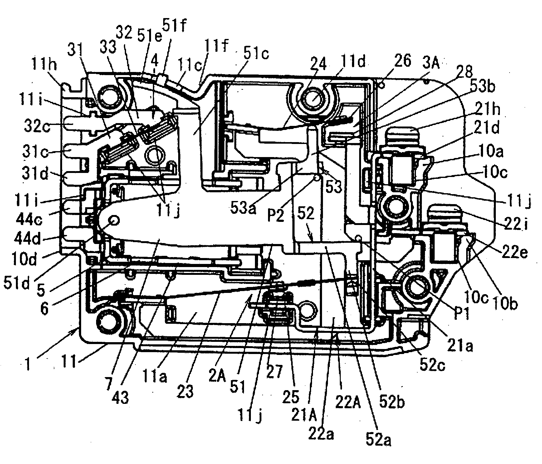
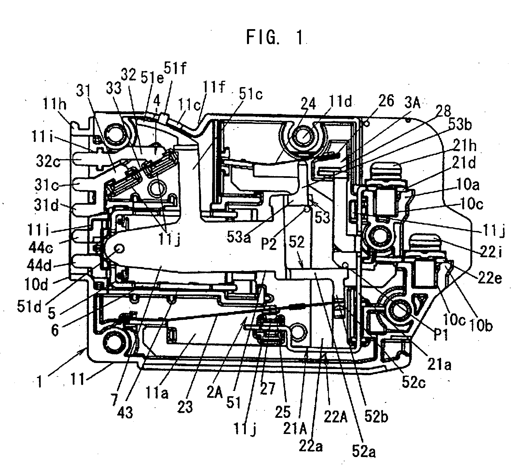
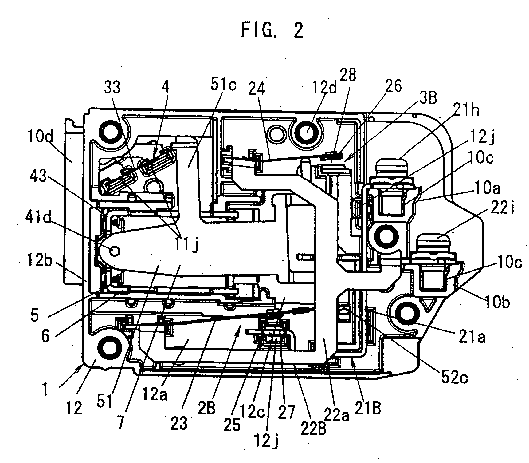
[0032] An electromagnetic relay according to an embodiment of the invention has a frame body 1 including a body 11, an intermediate body 12, and a cover 13, as shown in FIG. 3. Main contact units 2A and 2B, arc contact units 3A and 3B, an auxiliary contact unit 4, and an electromagnet 5, which are all described in detail later, are received in the frame body 1 (see FIGS. 1 and 2). The body 11, the intermediate body 12, and the cover 13 are made of, for example, poly butylene terephthalate (PBT).

[0033] The body 11 has a shape that an outer circumferential wall 11b protrudes along the rim of a side plate 11a from a surface (a top surface in FIG. 3) in the thickness direction of the side plate 11a. That is, the body 11 has a shape that one surface in the thickness direction of the side plate 11a is opened and the other surface is closed.

[0034] The in...


PUM


Abstract

Provided is an electromagnetic relay which does not require a braided wire for securing a current capacity of a main contact unit. The electromagnetic relay includes a main contact unit 2 A inserted into a power supply path to a load and an arc contact unit 3 A connected in parallel to the main contact unit 2A. An auxiliary contact unit 4 is electrically independent of the main contact unit 2 A and the arc contact unit 3A. The main contact unit 2 A includes a main fixed contact 27 fixed to a frame body 1 and a main contact spring 23 made of a leaf spring and fitted with a main mobile contact 25 which is attached to and detached from the main fixed contact 27. The arc contact unit 3 A and the auxiliary contact unit 4 are arranged adjacent to each other. The main contact spring 23 extends in a direction in which the arc contact unit 3 A and the auxiliary contact unit 4 are arranged. Therefore, the main contact spring 23 can be formed with a large length in the frame body 1 and the sectional area can be enhanced without increasing a spring constant, thereby not requiring a braided wire.

Description

BACKGRAOUND [0001] 1. Technical Field [0002] The present invention relates to an electromagnetic relay having a main contact unit which is inserted into a power supply path to a load and an arc contact unit which is connected in parallel to the main contact unit. [0003]2. Related Art [0004] Conventionally, as shown in FIG. 8, there is known an electromagnetic relay in which a main contact unit 2 and an arc contact unit 3 which are connected in parallel to each other are built in a frame body 1′ and the main contact unit 2 and the arc contact unit 3 are inserted into a power supply path to a load (see JP-A-2000-164100). [0005] The main contact unit 2 is made of a material having a small contact resistance and the arc contact unit 3 is made of a material having excellent adhesion resistibility. Therefore, by allowing the arc contact unit 3 to be closed after the main contact unit 2 is closed and allowing the arc contact unit 3 to be opened after the main contact unit 2 is opened, the ...

Claims


Application Information

Patent Timeline
IPC IPC(8): H01R13/62
CPCH01H9/38H01H50/026H01H50/326H01H50/54H01H50/541H01H50/56H01H51/2227H01H33/12
Inventor SASAKI, TOMOAKIKANEMOTO, NAOKIIMAI, TAKAFUMI
Owner MATSUSHITA ELECTRIC WORKS LTD
Features
  • Generate Ideas
  • Intellectual Property
  • Life Sciences
  • Materials
  • Tech Scout
  • Unparalleled Data Quality
  • Higher Quality Content
  • 60% Fewer Hallucinations
Learn More