Three-dimensional medical imaging apparatus

a medical imaging and three-dimensional technology, applied in the field of three-dimensional medical imaging equipment, can solve the problems of difficult to determine the direction of the observer, difficult to identify the tissue structure with the naked eye, and difficult to obtain any perspectiv

Active Publication Date: 2006-06-22
OLYMPUS CORP
View PDF3 Cites 17 Cited by
  • Summary
  • Abstract
  • Description
  • Claims
  • Application Information

AI Technical Summary

Benefits of technology

[0019] The present invention has been conceived in order to overcome the problems described above, and an object thereof is to provide a three-dimensional medical imaging apparatus that allows surgery to be performed wit

Problems solved by technology

With organs formed of minute tissue, such as the brain, it is difficult to identify their tissue structure with the naked eye, and therefore, the treatment of these organs is normally carried out under a microscope.
More specifically, as shown in FIGS. 12A to 12C, when the field angle is narrow, it is difficult to obtain any perspective, and therefore, it is difficult to determine that the sphere is approaching the observer.
As a result, it is possible to obtain a sense of depth in the images displayed on a two-dimensional monitor that is not capable of displaying three-dimensionally because the contribution made by this perspective is substantial.
Since surgical microscopes generally obtain depth information about the object under examination based on binocular paral

Method used


Image

  • Three-dimensional medical imaging apparatus
  • Three-dimensional medical imaging apparatus
  • Three-dimensional medical imaging apparatus

Examples


first embodiment

[0067] A first embodiment of the present invention will be described below with reference to FIGS. 1 to 3 and FIGS. 4A and 4B.

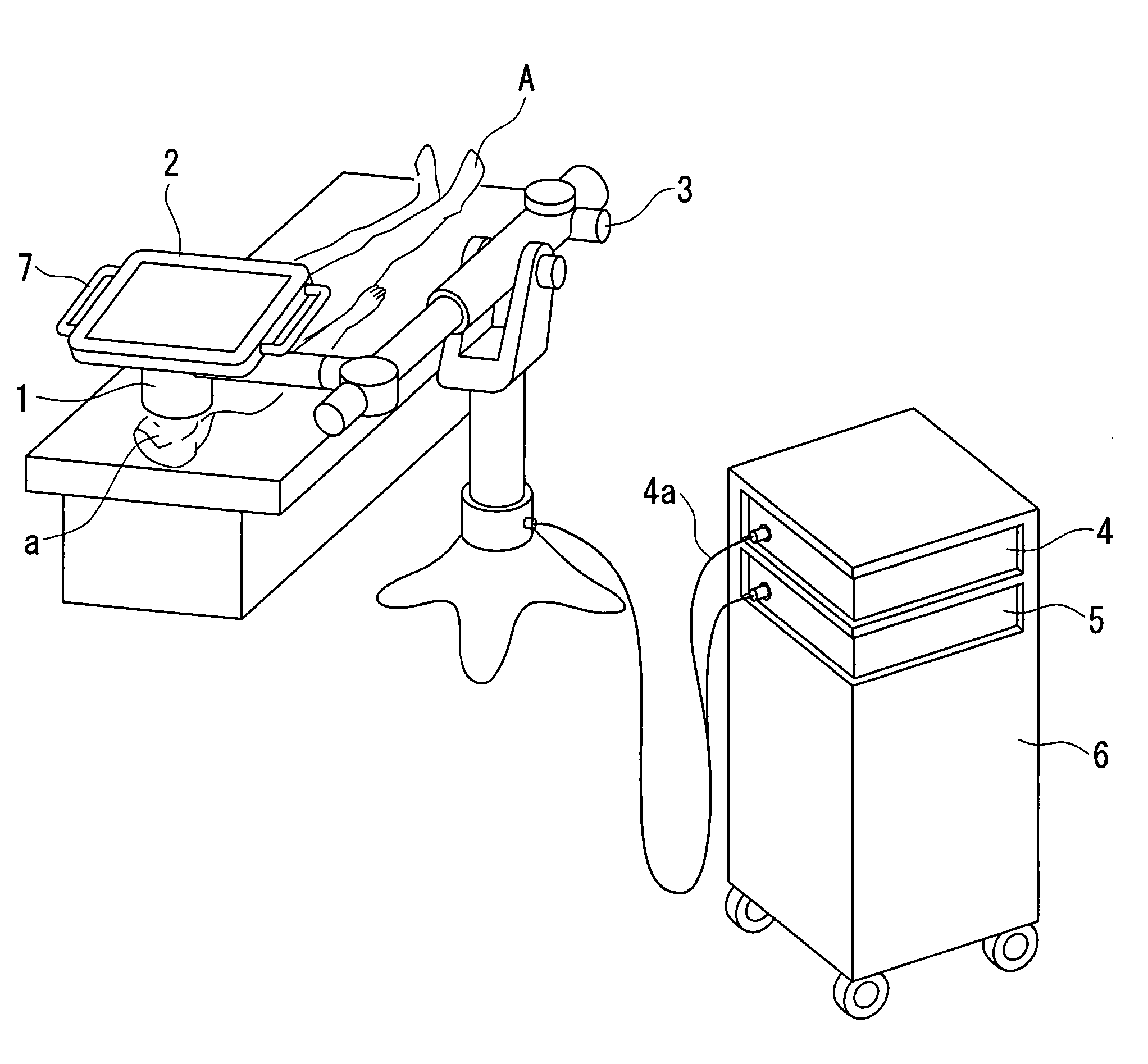
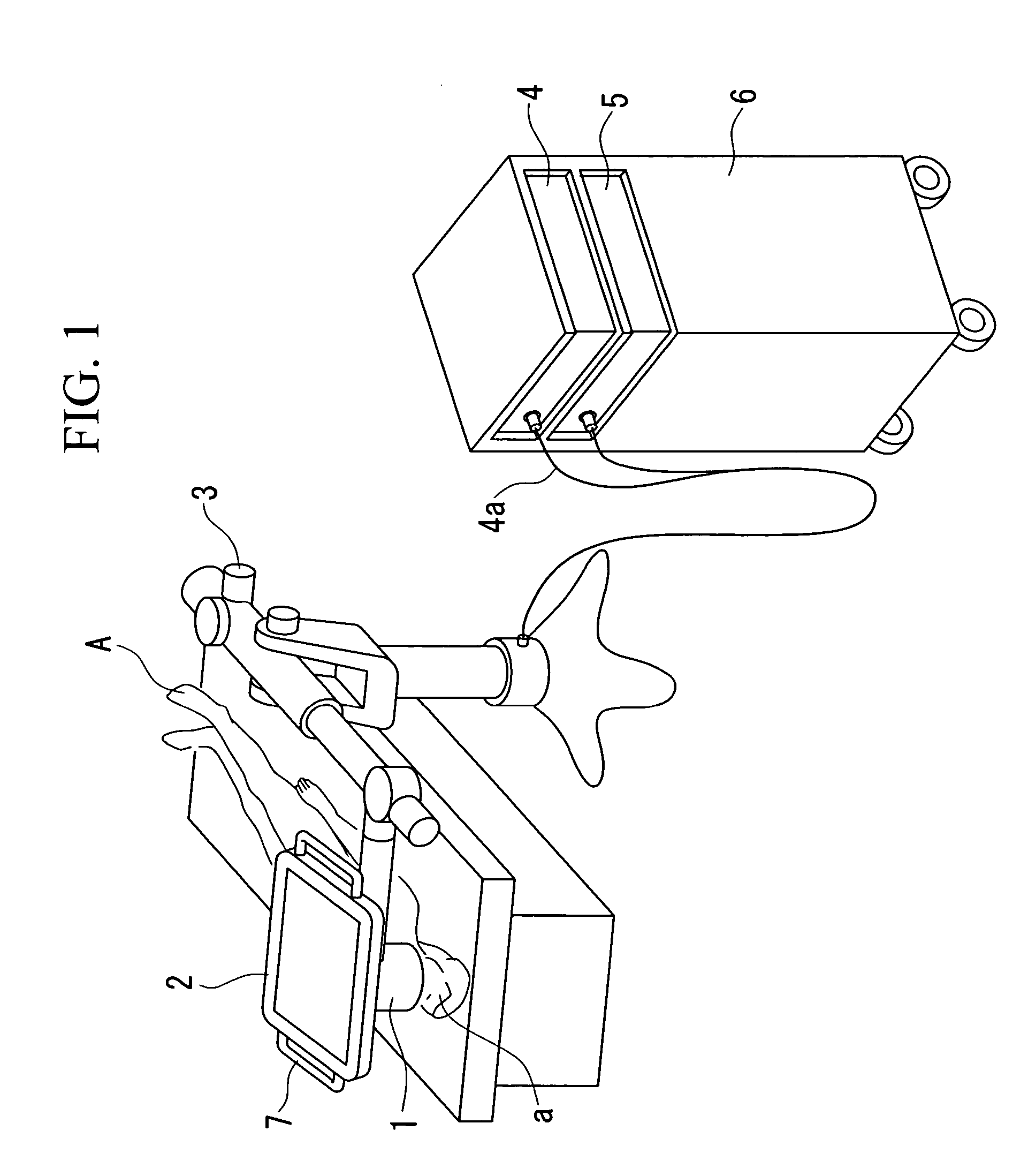
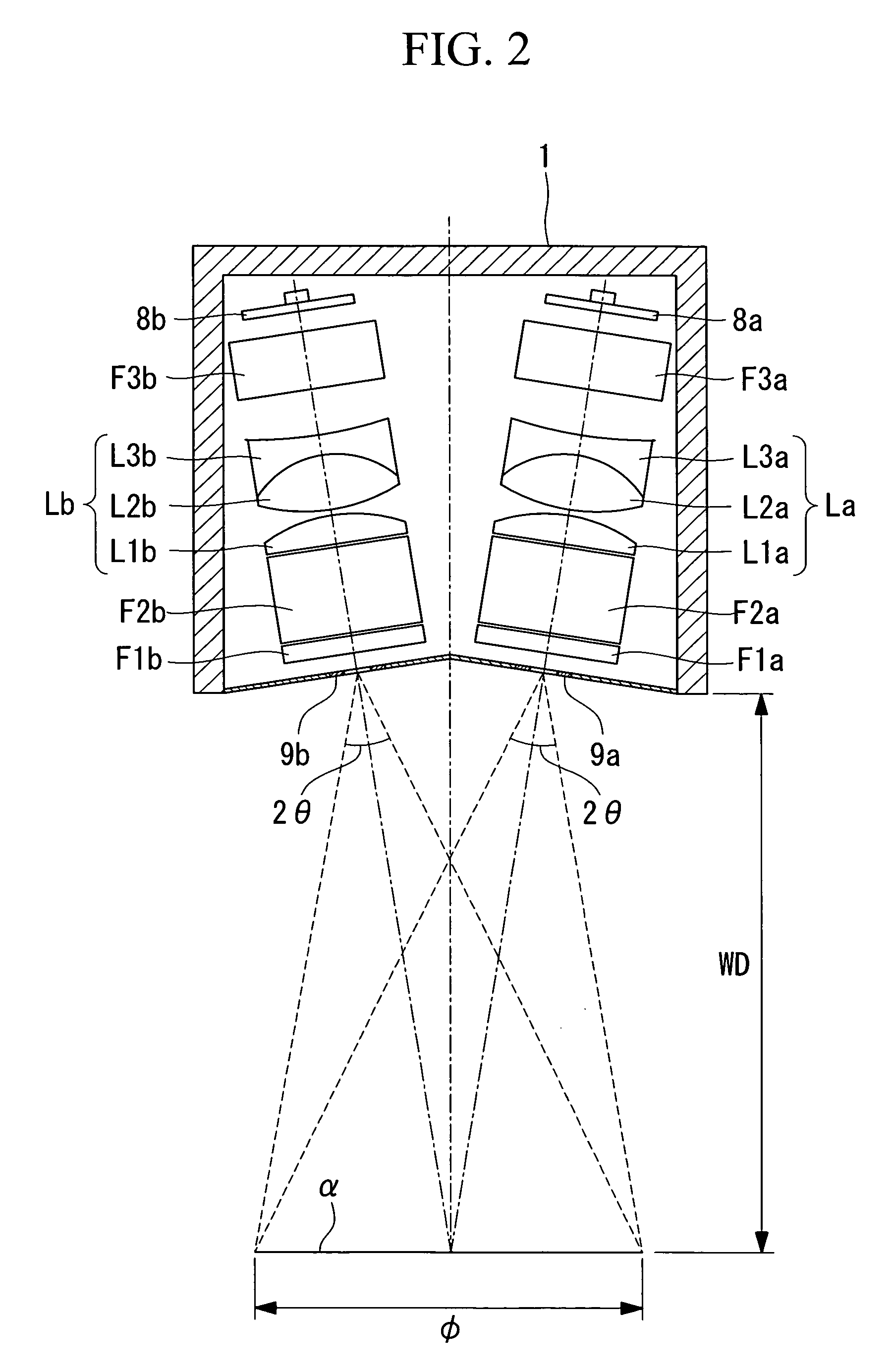
[0068]FIG. 1 is an overall view of the system, including a three-dimensional medical imaging apparatus according to this embodiment, FIG. 2 is a view showing the configuration of an image-acquisition optical system in the three-dimensional medical imaging apparatus according to this embodiment, FIG. 3 is a diagram illustrating the motion of a surgical instrument with respect to an operative site in a surgical procedure using the three-dimensional medical imaging apparatus, and FIGS. 4A and 4B are diagrams illustrating the operative area displayed on a display device when moving the surgical instrument.

[0069] The configuration of the overall system according to this embodiment will now be described with reference to FIG. 1.

[0070] In FIG. 1, reference numeral 1 indicates a three-dimensional medical imaging apparatus for examining an operative site a, which i...

second embodiment

[0083] A second embodiment of the present invention will now be described with reference to FIG. 5. Parts having the same names and reference numerals as those in the first embodiment are identical to those in the first embodiment, and a description thereof shall be omitted here.

[0084]FIG. 5 is a diagram showing the configuration of an image-acquisition optical system in the three-dimensional medical imaging apparatus 1 according to the present embodiment.

[0085] A right-eye objective optical system (objective optical system) La1 is constructed of three lenses L4a, L5a, and L6a, a right-eye collimator lens (collimator optical system) La2 is constructed of two lenses L7a and L8a, and a right-eye variable-magnification optical system (variable-magnification optical system) La3 is constructed of seven lenses L9a to L15a. Likewise, a left-eye objective optical system (objective optical system) Lb1 is constructed of three lenses L4b, L5b, and L6b, a left-eye collimator lens (collimator ...

third embodiment

[0095] A third embodiment of the present invention will now be described with reference to FIG. 6. Parts with the same names and same reference numerals as those in the first embodiment are identical to those in the first embodiment, and a description thereof shall thus be omitted here.

[0096]FIG. 6 is a diagram showing the configuration of an image-acquisition optical system in the three-dimensional medical imaging apparatus according to this embodiment.

[0097] An objective optical system Lc1 is constructed of two lenses L16 and L17, a variable-magnification optical system Lc2 is constructed of seven lenses L18 to L24, and an image-forming optical system Lc3 is formed of two lenses L25 and L26. Reference numeral L27 is a pupil-division prism, and reference numerals L28 and L29 are reflection prisms. A right-eye CCD (imaging device) 13a acquires an image of the object under examination from the reflection prism L28, and a left-eye CCD (imaging device) 13b acquires an image of the ob...


PUM


Abstract

By adding perspective information in addition to binocular parallax, the invention provides a three-dimensional medical imaging apparatus that allows surgery to be performed with a more natural three-dimensional view, similar to that achieved with the naked eye. The three-dimensional medical imaging apparatus includes an image-acquisition optical system and an imaging device for acquiring three-dimensional images of a subject. The image-acquisition optical system includes an objective optical system for forming an image of the subject at an image-forming plane, and an entrance pupil position of the image-acquisition optical system is disposed between the objective optical system and the subject.

Description

BACKGROUND OF THE INVENTION [0001] 1. Field of the Invention [0002] The present invention relates to a three-dimensional medical imaging apparatus used, for example, in surgical procedures, particularly in neurosurgery, ear, nose and throat surgery, orthopedic and plastic surgery, obstetric surgery, or ophthalmic surgery. [0003] This application is based on Japanese Patent Application No. 2004-350265, the content of which is incorporated herein by reference. [0004] 2. Description of Related Art [0005] In the related art, surgical microscopes are used to carry out magnified examination of minute operative sites in neurosurgery and so on. With organs formed of minute tissue, such as the brain, it is difficult to identify their tissue structure with the naked eye, and therefore, the treatment of these organs is normally carried out under a microscope. In neurosurgical procedures, which are carried out in very small regions on extremely critical and delicate tissue like blood vessels an...

Claims


Application Information

Patent Timeline
IPC IPC(8): A61B5/05H04N13/239
CPCA61B19/52A61B19/5223H04N13/0239A61B90/36A61B90/20H04N13/239
Inventor NAMII, YASUSHIHIROSE, KENJIYASUNAGA, KOJI
Owner OLYMPUS CORP
Why Eureka
Try Eureka