System and method for hydrogen production

a hydrogen production and hydrogen technology, applied in the field of hydrogen production, can solve the problem of compactness of conventional smr systems

Inactive Publication Date: 2006-06-29
GENERAL ELECTRIC CO
View PDF40 Cites 32 Cited by
  • Summary
  • Abstract
  • Description
  • Claims
  • Application Information

AI Technical Summary

Problems solved by technology

Conventional SMR systems are not compact since large heat exchange surface area are required to provide heat to the endothermic steam methane reforming reaction.

Method used


Image

  • System and method for hydrogen production
  • System and method for hydrogen production
  • System and method for hydrogen production

Examples


Embodiment Construction

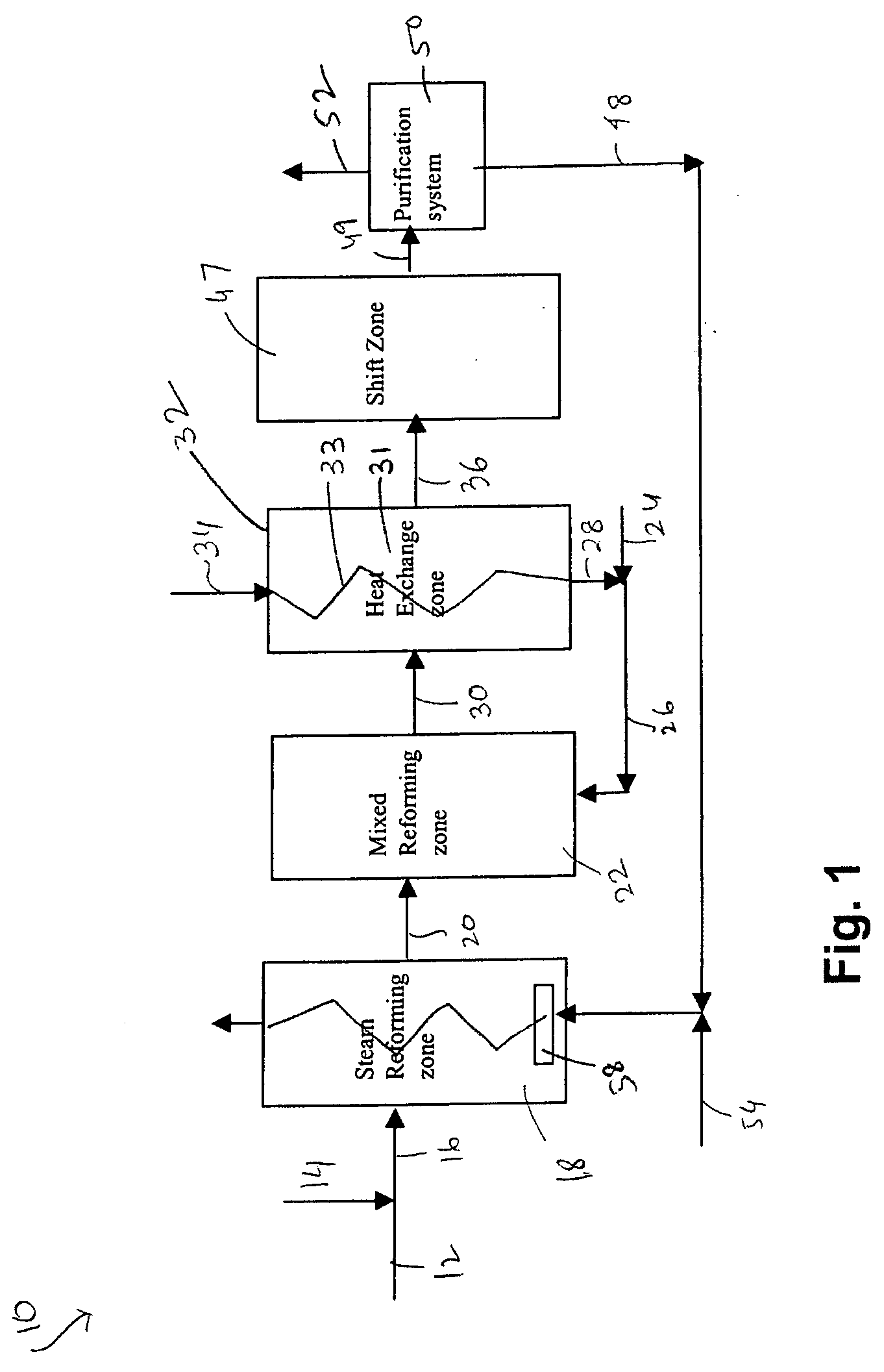
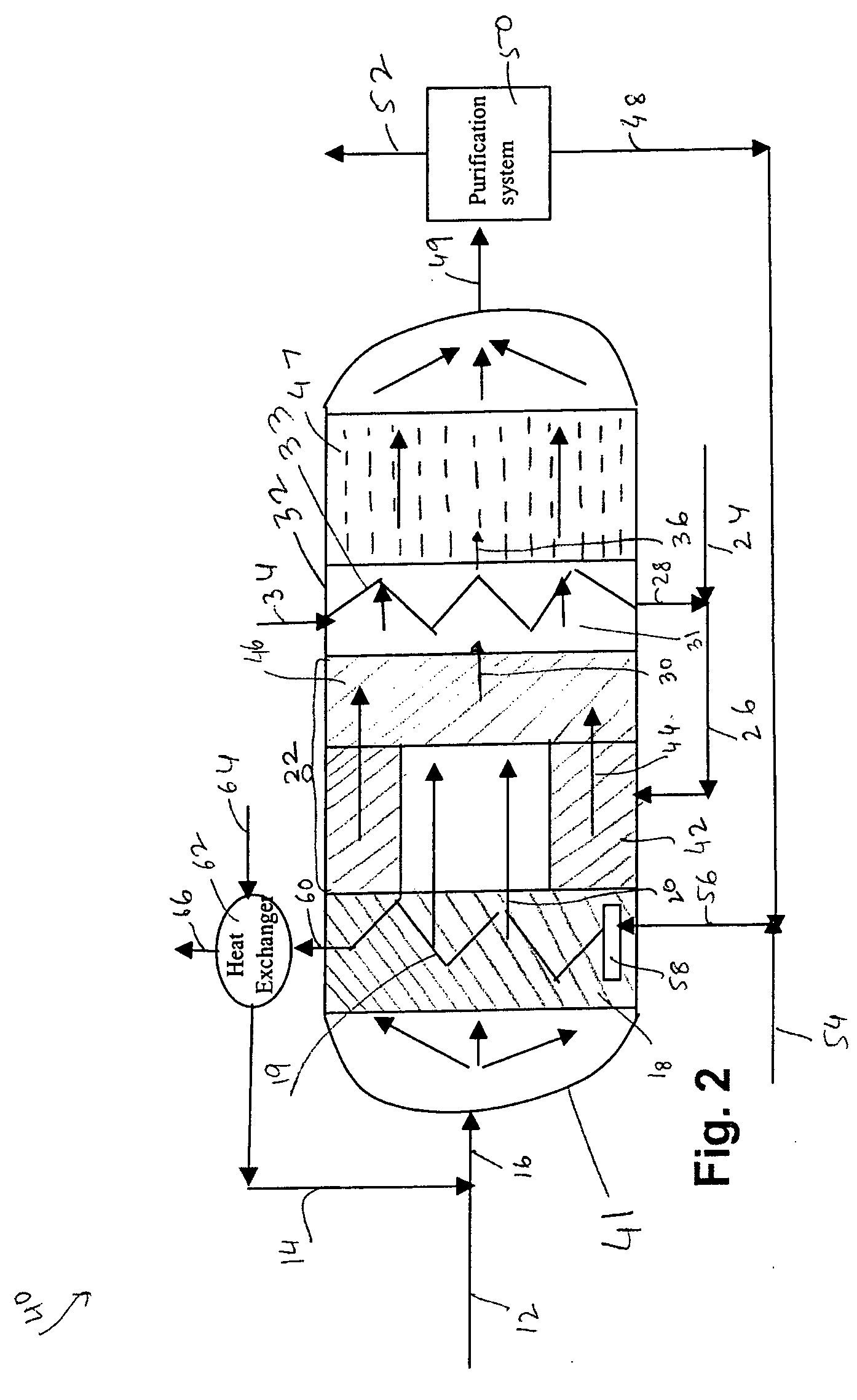
[0019]FIG. 1 represents an exemplary system 10 for producing hydrogen comprising at least one steam reforming zone 18 and at least one mixed reforming zone 22. The steam reforming zone 18 is configured to receive a first fuel 12 and steam 14 and produce a first reformate gas stream 20 comprising hydrogen. In one embodiment, the first fuel 12 and the steam 14 are mixed to form a mixed stream 16, which mixed stream 16 is introduced into the steam reforming zone 18. The first reformate gas stream 20 is sent to the mixed reforming zone 22 to complete the reforming process. The mixed reforming zone 22 comprises a catalyst for performing catalytic partial oxidation. In one embodiment, the mixed reforming zone comprises catalysts for performing both catalytic partial oxidation (CPO) and steam reforming functions. The mixed reforming zone 22 is configured to receive an oxidant 28 and optionally a second fuel 24 and to produce a second reformate gas stream 30 comprising hydrogen. The mixed r...


PUM

PropertyMeasurementUnit
temperatureaaaaaaaaaa

Abstract

A system for production of hydrogen comprises at least one steam reforming zone configured to receive a first fuel and steam to produce a first reformate gas stream comprising hydrogen using a steam reforming process. The system further comprises a mixed reforming zone configured to receive an oxidant to produce a second reformate gas stream comprising hydrogen, wherein the first reformate gas stream is sent to the mixed reforming zone to complete the reforming process.

Description

BACKGROUND OF THE INVENTION [0001] This invention relates to production of hydrogen from fuels comprising at least one of carbon, oxygen or hydrogen and more specifically to production of hydrogen in a compact reformer. [0002] Currently, the most cost effective method of producing hydrogen is centralized steam reforming of fuels such as natural gas and methanol. Rising energy prices and concern for the environment are prompting increased attention to hydrogen as a renewable energy source. Hydrogen has been proposed as a clean fuel for the future with applications in vehicle and stationary power (electric utility). [0003] The largest volumes of merchant hydrogen are consumed in ammonia plants, in refineries and in methanol production. Only a fraction of hydrogen is currently used for energy purposes. However, hydrogen's share in the energy market is increasing with the implementation of fuel cell systems and the growing demand for low emission or zero-emission fuels. [0004] Steam met...

Claims


Application Information

Patent Timeline
Patent Type & Authority Applications(United States)
IPC IPC(8): B01J7/00
CPCB01J8/0257B01J8/0438B01J8/0442B01J8/0465B01J8/0469B01J8/048B01J8/0496B01J8/067B01J2208/00132B01J2208/00194B01J2208/00203B01J2208/00212B01J2208/00309B01J2208/00362B01J2208/00504B01J2208/0053B01J2208/00849B01J2208/025C01B3/382C01B3/386C01B2203/0233C01B2203/0244C01B2203/0261C01B2203/0283C01B2203/0288C01B2203/04C01B2203/0405C01B2203/0415C01B2203/043C01B2203/046C01B2203/0475C01B2203/0827C01B2203/0838C01B2203/1223C01B2203/1229C01B2203/1235C01B2203/143C01B2203/82C01B2203/84
Inventor KUMAR, RAVI VIPPERIAZAMANSKY, VLADIMIREITENEER, BORIS NIKOLAEVICHBARGE, SHAWN DAVIDKULKARNI, PARAG PRAKASHLIU, KE
Owner GENERAL ELECTRIC CO
Why Eureka
Try Eureka