Sensor

a technology of sensors and connectors, applied in the field of sensors, can solve the problems of disconnection of the base end, broken base end of the lead, loose lead, etc., and achieve the effect of improving the bonding strength of each lead to the sensor element, reducing the electric resistance value in the connected portion, and improving the connection strength of the end portion of each lead

Inactive Publication Date: 2006-06-29
TDK CORPARATION
View PDF3 Cites 13 Cited by
  • Summary
  • Abstract
  • Description
  • Claims
  • Application Information

AI Technical Summary

Benefits of technology

[0009] The present invention has an object of providing a sensor which is enabled to prevent in advance the disconnection of the leads in a manufacturing procedure and in a state where it is in use, and can be used at a high precision.
[0012] Moreover, the sensor of the present invention enables intrusion of electromagnetic noise to be reduced because the lead is bent plural times. For example, in a gas sensor, there are many cases where the temperature is controlled by causing the current to flow from one lead to the heater, and simultaneously therewith a change in the electric potential or resistance of the sensor is detected through the other lead. In this case, the direct current is employed for the sensor, and the control of the heater and the detection of a change in the electric potential or the resistance of the sensor tend to become unstable when the electromagnetic noise having a certain frequency is superimposed upon this direct current. Most of such kinds of the electromagnetic noise often intrude into the sensor through each lead.
[0013] On the other hand, in the present invention, each lead has an inductance because it is bent plural times. That is, intrusion of the noise into the sensor can be suppressed because each lead has the impedance against the electromagnetic noise of which frequency is higher than that of direct current This enables the high precision thermal control and the exact detection of a change in the electric potential or the resistance, or the like.
[0017] The end portion of each lead configured as mentioned above does not falls off the connected portion unintentionally, and a connecting strength of the end portion of each lead is improved. Moreover, an electric resistance value in the connected portion is reduced.
[0018] Moreover, the stopper structure may be configured as follows. That is, the sensor element is provided with a plurality of through-holes, and the end portion of each of the plurality of the leads may pass through the corresponding through-hole. Allowing the end portion of each lead to pass through the through-hole in such a manner causes the bonding strength of each lead to the sensor element to be improved.

Problems solved by technology

Therefore, in a manufacturing procedure, when a load (weight) for grasping the lead acts upon a base end of the lead at the time of connecting the tip of each lead to each stem pin after connecting the base end of each lead to the sensor element, the base end of the lead is broken and the disconnection of the base end occurs in some cases.
Furthermore, for example, in the gas sensor, when a heater attached to the gas sensor element generates heat in a state where the gas sensor is in use, each lead becomes loose due to thermal expansion.
In addition to the foregoing structural problem, there exists a problem that an external electromagnetic wave intrudes into the sensor element through each lead, thereby causing a thermal control and a detection precision of the sensor to deteriorate.

Method used


Image

  • Sensor
  • Sensor
  • Sensor

Examples


Embodiment Construction

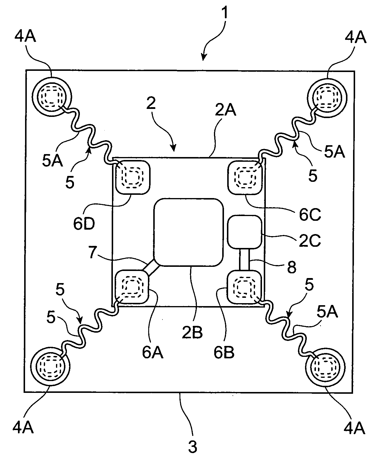
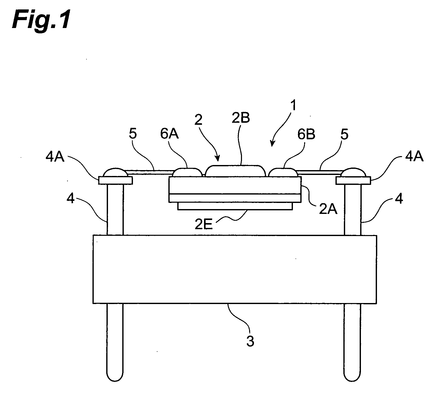
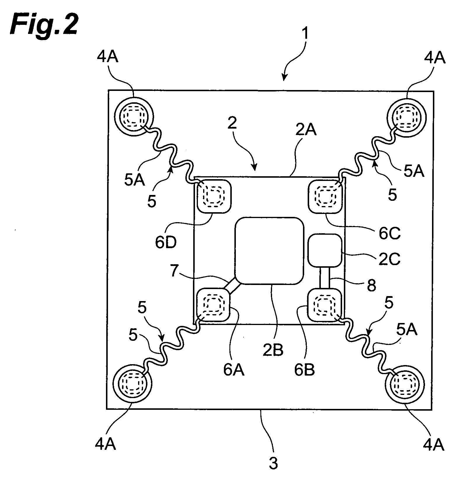
[0048] Hereinafter, embodiments in which the gas sensor, out of the sensors according to the present invention, is exemplified will be explained by making a reference to the accompanied drawings. In the figures to which a reference is made, FIG. 1 is a side-view illustrating a schematic structure of the gas sensor according to one embodiment, and FIG. 2 is a plan view of the gas sensor shown in FIG. 1.

[0049] A gas sensor 1 of one embodiment shown in FIG. 1 and FIG. 2 is a gas sensor for detecting the concentration of, for example, carbon dioxide (CO2) as a specific gas in the atmospheric gas. The gas sensor 1 comprises a gas sensor element 2 for detecting carbon dioxide (CO2). This gas sensor element 2 is connected to four stem pins 4 via four leads 5 respectively. The stem pins 4 are fastened in the vicinity of four comers of a base plate 3 in a penetration state. The gas sensor element 2 is supported in a suspension state by each of stem pins 4 via each of the leads 5.

[0050] As ...


PUM


Abstract

The sensor according to an embodiment of the present invention comprises a base, a plurality of pins fixed to the base, a sensor element, and a plurality of leads connecting the sensor element to the plurality of the pins. The sensor element is supported by the plurality of the pins via the plurality of the leads. Each of the plurality of the leads is provided along a straight line extending between a connected pin, out of the plurality of the pins, and the sensor element, and is bent plural times between the connected pin and the sensor element.

Description

BACKGROUND OF THE INVENTION [0001] 1. Field of the Invention [0002] The present invention relates to a sensor having a sensor element, and, for example, to a sensor having a gas sensor element for detecting a specific gas. [0003] 2. Related Background of the Invention [0004] Generally, in various sensors such as an optical sensor, a magnetic sensor, a temperature sensor, and an acoustic sensor, a sensor element is arranged so as to be independent of a housing. The reason is that the sensor element is adapted not to receive an influence (optical reflection, magnetic field, heat, vibration, etc.) from a housing of the sensor element. [0005] As the sensor of this type, there exists a gas sensor for detecting concentration of a specific gas in an atmospheric gas. As for the gas sensor, a gas sensor is conventionally known in general that includes a gas sensor element for detecting a specific gas and has a structure in which this gas sensor element is connected to each of a plurality of ...

Claims


Application Information

Patent Timeline
Patent Type & Authority Applications(United States)
IPC IPC(8): H01C1/01
CPCG01N27/12G01N27/4077
Inventor ONO, SHIZUKO
Owner TDK CORPARATION
Why Eureka
Try Eureka