Optical scanning device and image display apparatus using the same

a scanning device and scanning technology, applied in the field of optical scanning devices and scanning type image display apparatus, can solve the problems of slow speed of optical scanning on the scanning surface on the periphery, large optical system, and large volume, and achieve high accuracy scanning on the scanning surface and constant speed

Inactive Publication Date: 2006-06-29
CANON KK
View PDF12 Cites 51 Cited by
  • Summary
  • Abstract
  • Description
  • Claims
  • Application Information

AI Technical Summary

Benefits of technology

[0014] An object of the present invention is to provide an optical scanning device capable of highly accurately scanning on a scanning surface at constant speed when an optical scanning is two-dimensionally performed on the scanning surface by using a scanning device to sine-wave drive.

Problems solved by technology

In case the scanning device with sine-wave drive such as the galvanic mirror, the MEMS device, and the like is used, there has been generally known that a speed to optical-scan on the scanning surface becomes slow on the periphery.
Further, there has been generally known that when the optical scan is two-dimensionally performed by using such a scanning device, a scanning distortion is generated on the two-dimensional image formed on the scanning surface.
In the optical scanning device disclosed in Japanese Patent Application Laid-Open No. 2001-281583, when an attempt is made to secure both of a two-dimensional translatory scanning property and a constant speed scanning property by the optical characteristic of the scanning optical system, the optical system becomes complicated and large-sized.
Further, since light quantity distribution on the scanning surface is in a relationship of inversely proportional to the optical scanning speed, unevenness in light quantity is generated so as to degrade the appearance quality of the image.

Method used


Image

  • Optical scanning device and image display apparatus using the same
  • Optical scanning device and image display apparatus using the same
  • Optical scanning device and image display apparatus using the same

Examples


first embodiment

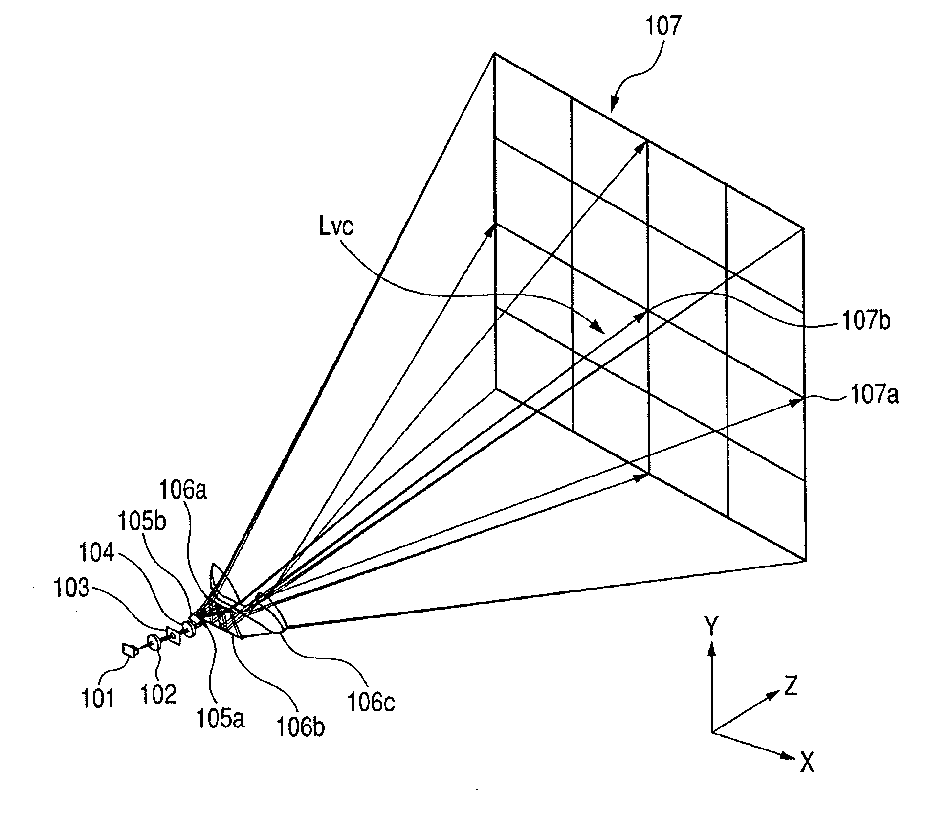
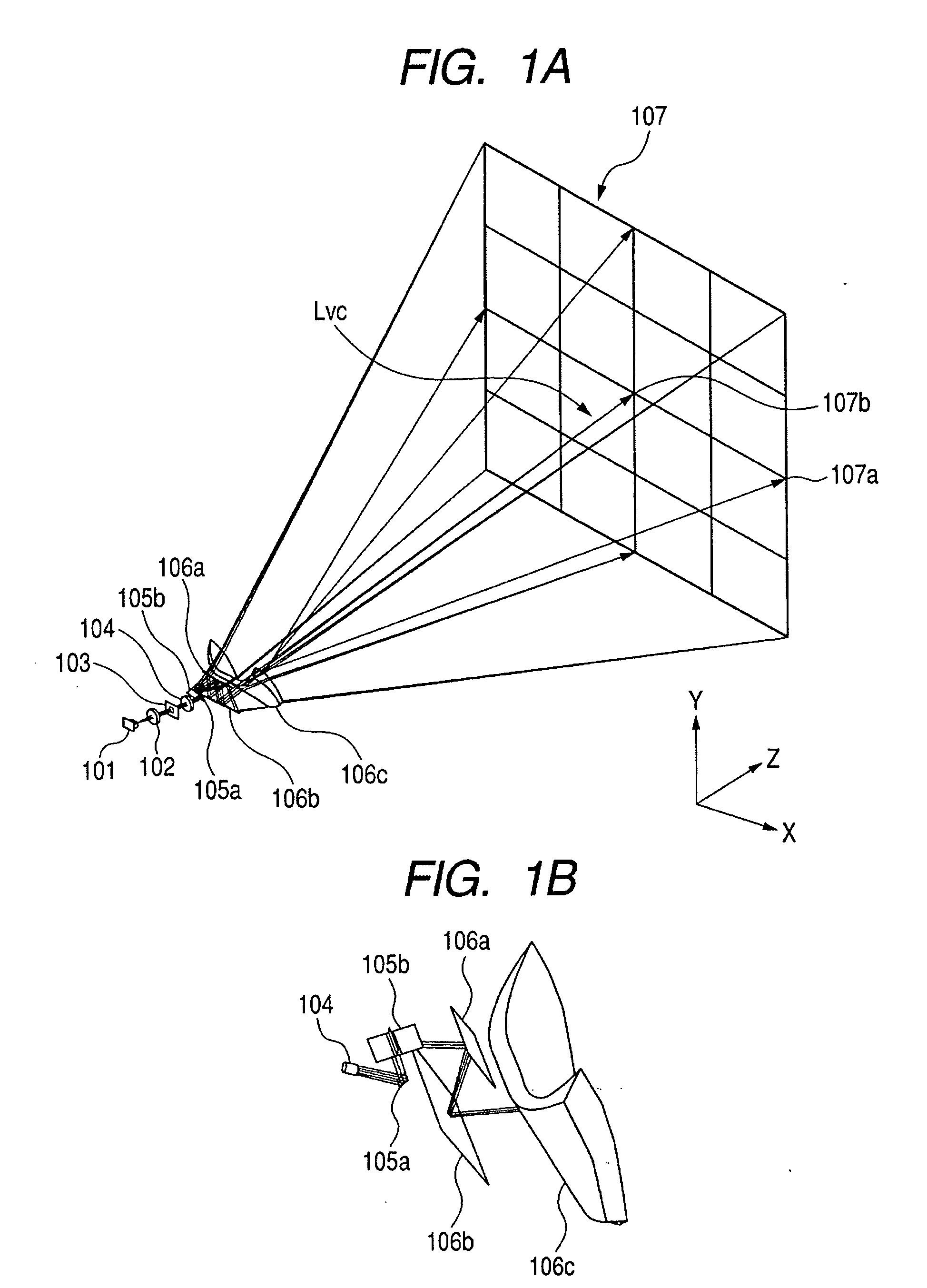
[0063]FIGS. 1A and 1B are main part perspective views respectively of an optical scanning device of a first embodiment, and an enlarged perspective view of a portion.

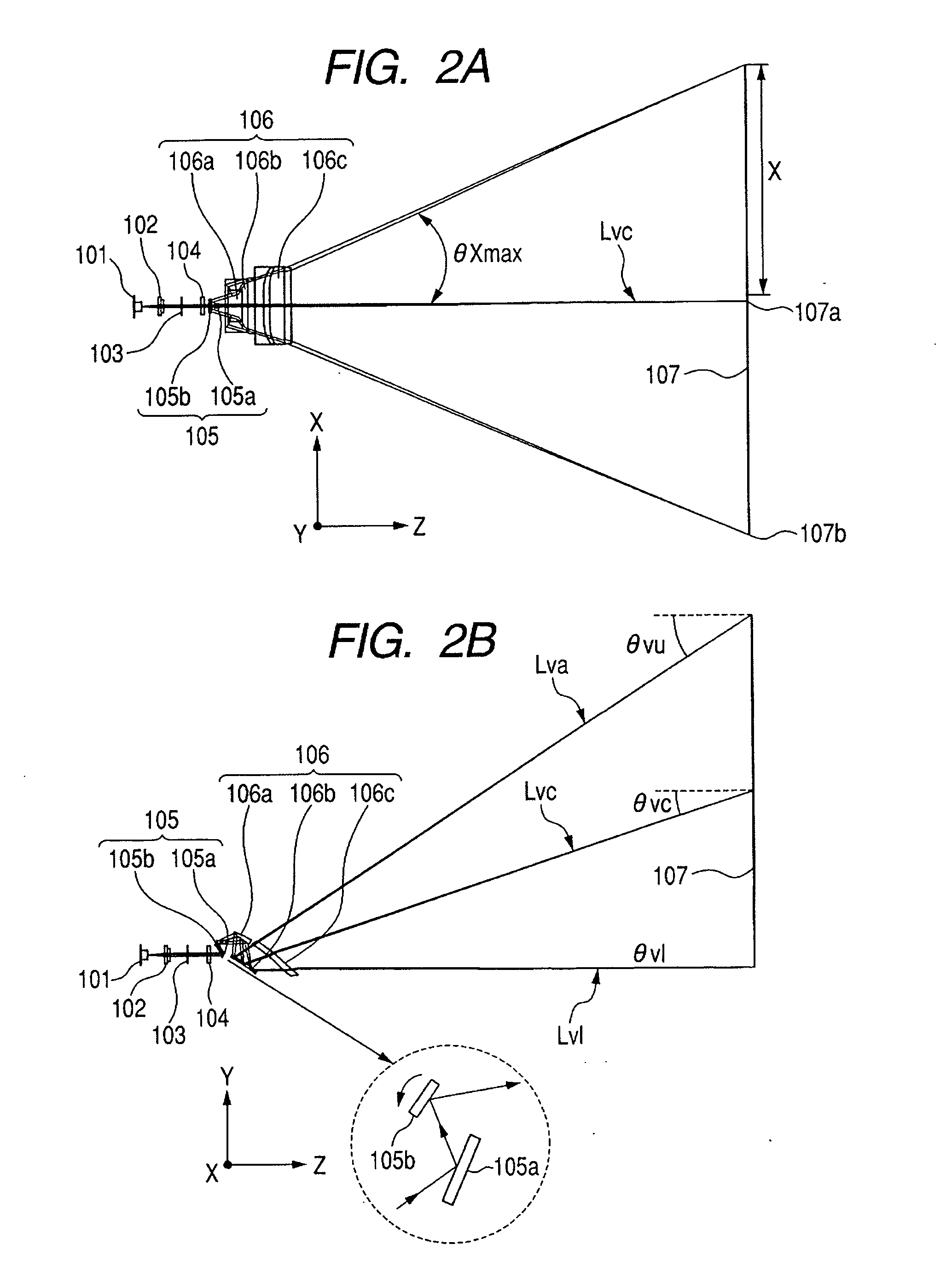
[0064]FIG. 2A is a main part cross sectional view (horizontal scanning cross sectional view, XZ cross sectional view) in a horizontal scanning direction (first scanning direction) of the optical scanning device of a first embodiment. FIG. 2B is a main part cross sectional view (vertical scanning cross sectional view, YZ cross sectional view) in a vertical scanning direction (second scanning direction) of the optical scanning device of the first embodiment.

[0065] In FIGS. 1A, 1B, 2A, and 2B, reference numeral 101 denotes a light source unit comprising a semiconductor laser, for example, radiating a red color light. The light source unit 101 emits an optically modulated light beam based on image information. A divergent light beam emitted from the light source unit 101 is converted into an approximately parallel light b...

second embodiment

[0212]FIG. 23A is a horizontal scanning cross sectional view in an optical scanning device of a second embodiment, and FIG. 23B is its vertical scanning cross sectional view.

[0213] In FIGS. 23A and 23B, reference numeral 201 denotes a light source unit comprising three color lasers of a green color semiconductor laser 201a radiating a green color light, a red color semiconductor laser 201b radiating a red color light, and a blue color semiconductor laser 201c radiating a blue color light. The three color divergent light beams emitted from the light source unit 201 are converted into parallel light beams by the corresponding condenser lenses 202a, 202b, and 202c, respectively, and are limited in each light beam width by aperture-stops 203a, 203b, and 203c, respectively. After that, the laser beams of the red color, the green color, and the blue color are synthesized into a while color light beam by a dichroic prism 208, which is beam synthesizing means.

[0214] The synthesized white ...

third embodiment

[0255]FIG. 34A shows a horizontal scanning cross sectional view of an optical scanning device of a third embodiment, and FIG. 34B shows its vertical scanning cross sectional view.

[0256] In FIGS. 34A and 34B, a divergent light beam emitted from a light source unit 301 is converted into a parallel light beam or an approximately parallel light beam by a condenser lens 302, and is further limited in light beam width by an aperture stop 303. The light beam having passed through the aperture stop 303 is converted into a convergent light beam having a desired convergence degree by a convergence optical system 304, and becomes an incident light beam to enter a scanning unit 305 to be described later. The scanning unit 305 is constituted by a deflector capable of scanning in a secondary dimensional direction. This secondary dimensional scanning unit 305 scans the light beam from the light source unit 301 in a horizontal scanning direction and a vertical scanning direction. The scanning unit...


PUM


Abstract

An optical scanning device is disclosed, which comprises a light source unit, a scanning unit for scanning a scanning surface with a light from the light source unit in a first direction and a second direction orthogonal to the first direction, and an optical unit for guiding the scanning light onto the scanning surface. The scanning unit has a deflection surface which sine-wave-drives in the first direction. The optical unit has an optical surface whose arbitrary cross section in the first direction has a shape where a second order derivative of the function representing a shape of the cross section changes so as to diverge a light stronger as toward the periphery from the center. And the optical surface is configured by arranging the shape of each cross section in the first direction in the second direction.

Description

BACKGROUND OF THE INVENTION [0001] 1. Field of the Invention [0002] The present invention relates to an optical scanning device and a scanning type image display apparatus using the same, and in particular, it projects and displays a two-dimensional image on a scanning surface, for example, a screen surface by two-dimensionally scanning a light by a scanning device. [0003] 2. Description of the Related Art [0004] A variety of optical scanning devices have been proposed, in which a spot (beam spot) of the light beam emitted from a light source is two-dimensionally optically scanned on a scanning surface, and by the residual image effect, a two-dimensional image is formed (for example, see Japanese Patent Application Laid-Open Nos. 2001-281583 and H11-84291) [0005] In the optical scanning device, as means to scan the light beam from the light source, a polygon mirror, a galvanic mirror, a MEMS device prepared by a MEMS (Micro Electron Mechanical Systems) technology, and the like have ...

Claims


Application Information

Patent Timeline
Patent Type & Authority Applications(United States)
IPC IPC(8): G02B26/08
CPCG02B26/101H04N9/3129G02B26/10
Inventor ISHIHARA, KEIICHIRO
Owner CANON KK
Why Eureka
Try Eureka