Light-emitting unit with enhanced thermal dissipation and method for fabricating the same

Inactive Publication Date: 2006-06-29
LG DISPLAY CO LTD
View PDF6 Cites 71 Cited by
  • Summary
  • Abstract
  • Description
  • Claims
  • Application Information

AI Technical Summary

Benefits of technology

[0014] An object of the present invention is to provide a light-emitting unit with enhanced thermal dissipation and a method for fabricating the same with improved heat transfer.
[0015] Another object of the present invention is to provide light-emitting unit with enhanced thermal di

Problems solved by technology

An LED does not have perfect light-emission efficiency in converting electrical energy to light energy.
Consequently, when the heat generated by the LED is not rapidly dissipated to the outside, a desired-color light cannot be obtained due to color shift by the LED.
However, there i

Method used


Image

  • Light-emitting unit with enhanced thermal dissipation and method for fabricating the same
  • Light-emitting unit with enhanced thermal dissipation and method for fabricating the same
  • Light-emitting unit with enhanced thermal dissipation and method for fabricating the same

Examples


Embodiment Construction

[0031] Reference will now be made in detail to the preferred embodiments of the present invention, examples of which are illustrated in the accompanying drawings. Wherever possible, the same reference numbers will be used throughout the drawings to refer to the same or like parts.

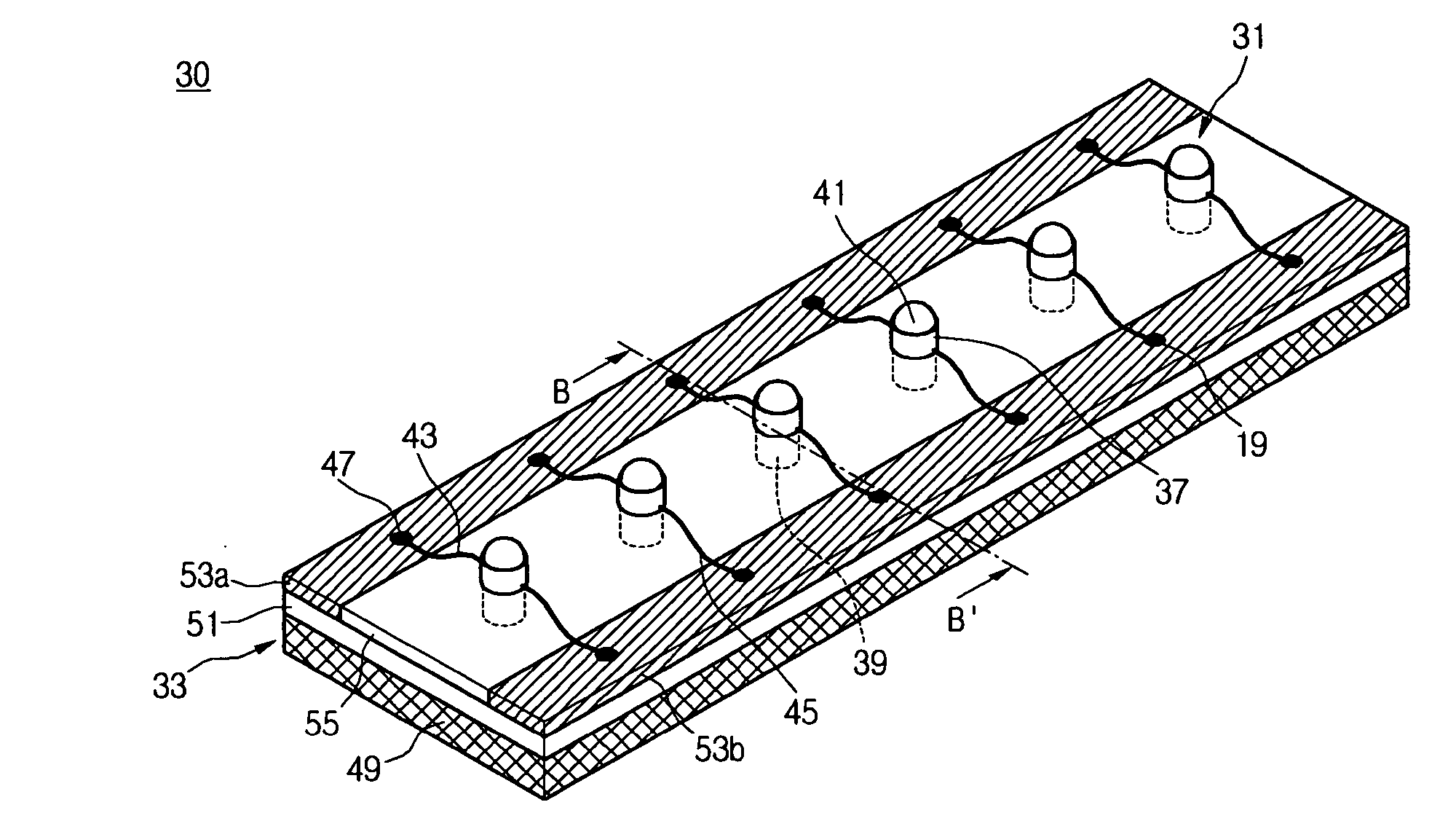
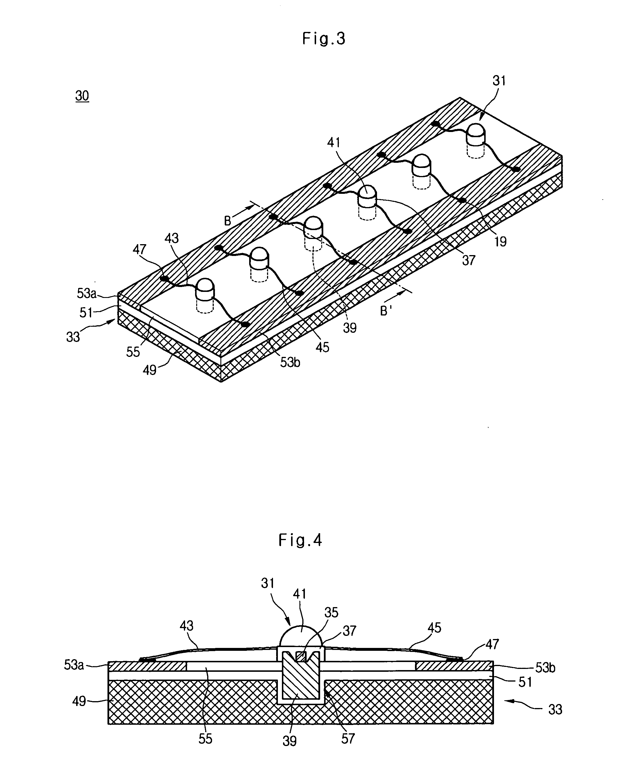
[0032]FIG. 3 is a perspective view of a light-emitting package according to an embodiment of the present invention, FIG. 4 is a cross-sectional view taken along line B-B′ in FIG. 3, and FIG. 5 is a perspective view of a light-emitting unit illustrated in FIG. 3. Referring to FIGS. 3 to 5, a light-emitting package 30 includes a PCB 33, and a plurality of light-emitting units 31 installed on the PCB 33. The PCB 33 can be a metal core printed circuit board (MCPCB) that has a heat sink plate for dissipating heat and an electrode pattern for supplying electric power.

[0033] The light-emitting units can be a plurality of R / G / B light-emitting units that are arranged on the PCB 33 and are spaced apart from one ano...


PUM


Abstract

A light-emitting unit includes a housing, a heat sink member having surfaces outside of the housing, a light-emitting diode attached to the heat sink member, and a molding member formed on the housing.

Description

[0001] The present invention claims the benefit of Korean Patent Application No. 112693 / 2004 filed in Korea on Dec. 27, 2004, which is hereby incorporated by reference in its entirety. BACKGROUND OF THE INVENTION [0002] 1. Field of the Invention [0003] The present invention relates to a light-emitting device, and more particularly, to a light-emitting unit with enhanced thermal dissipation and method for fabricating the same. Although the present invention is suitable for a wide scope of applications, it is particularly suitable for dissipating heat from a light-emitting unit that uses a light emitting diode as a light source. [0004] 2. Discussion of the Related Art [0005] In general, a light-emitting device can be used as a high-brightness light source for flashlights, a backlight source for portable electronic devices, a light source for electronic display boards, an illumination light source for switches, a beaconlight, a traffic signal light, and so on. For example, a light-emit...

Claims


Application Information

Patent Timeline
IPC IPC(8): F21V29/00F21K99/00
CPCF21K9/00F21L4/027F21S4/003F21V29/004F21W2111/00F21V29/89H05K1/021H05K1/056H05K1/182H05K2201/10106F21V29/20F21Y2101/02F21S4/20F21Y2115/10F21V29/70
Inventor PARK, HEE JEONG
Owner LG DISPLAY CO LTD
Why Eureka
Try Eureka