X-ray ct device

a ct device and x-ray technology, applied in tomography, instruments, applications, etc., can solve the problems of high cost of ct apparatus using electron beam, unsuitable clinical diagnosis, large apparatus, etc., and achieve the effect of reducing the noise level differen

Active Publication Date: 2006-06-29
FUJIFILM HEALTHCARE CORP
View PDF11 Cites 23 Cited by
  • Summary
  • Abstract
  • Description
  • Claims
  • Application Information

AI Technical Summary

Benefits of technology

[0017] According to a ninth aspect of the invention, the reconstruction means includes filter mean

Problems solved by technology

It is known that when scanning and reconstruction are not done following the beat of the heart in heart region imaging, a pseudo-image called a motion artifact and blurring occur, which is unsuitable for clinical diagnosis.
However, the cost of this CT apparatus using an electron beam is high, the CT apparatus is large, it is necessary to dispose the CT apparatus in addition to an existing X-ray CT apparatus, and there is the potential for the CT apparatus to become a burden in terms of equipment investment.
However, retrospective segmented reconstruction has the probl

Method used


Image

  • X-ray ct device
  • X-ray ct device
  • X-ray ct device

Examples


embodiment 1

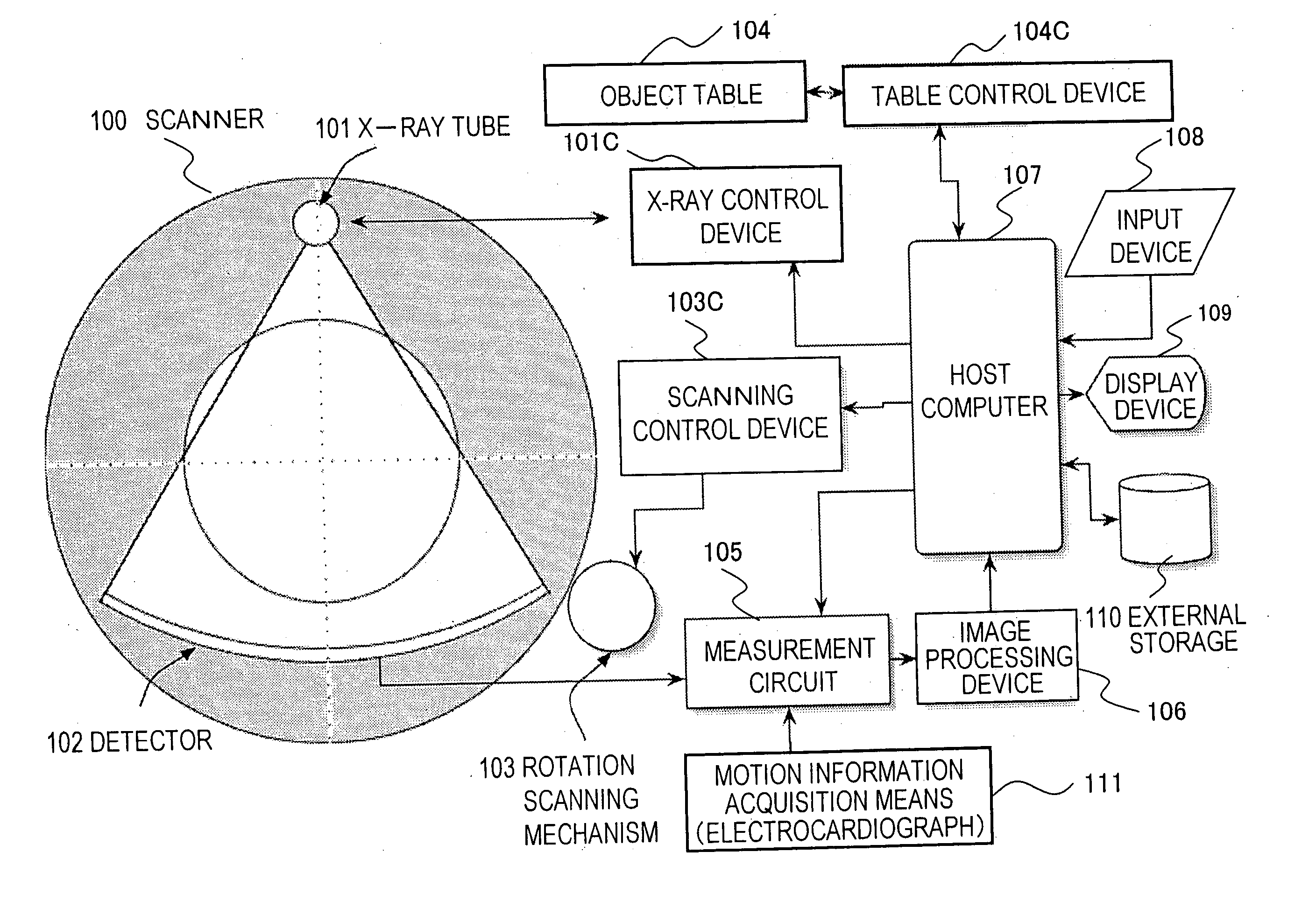
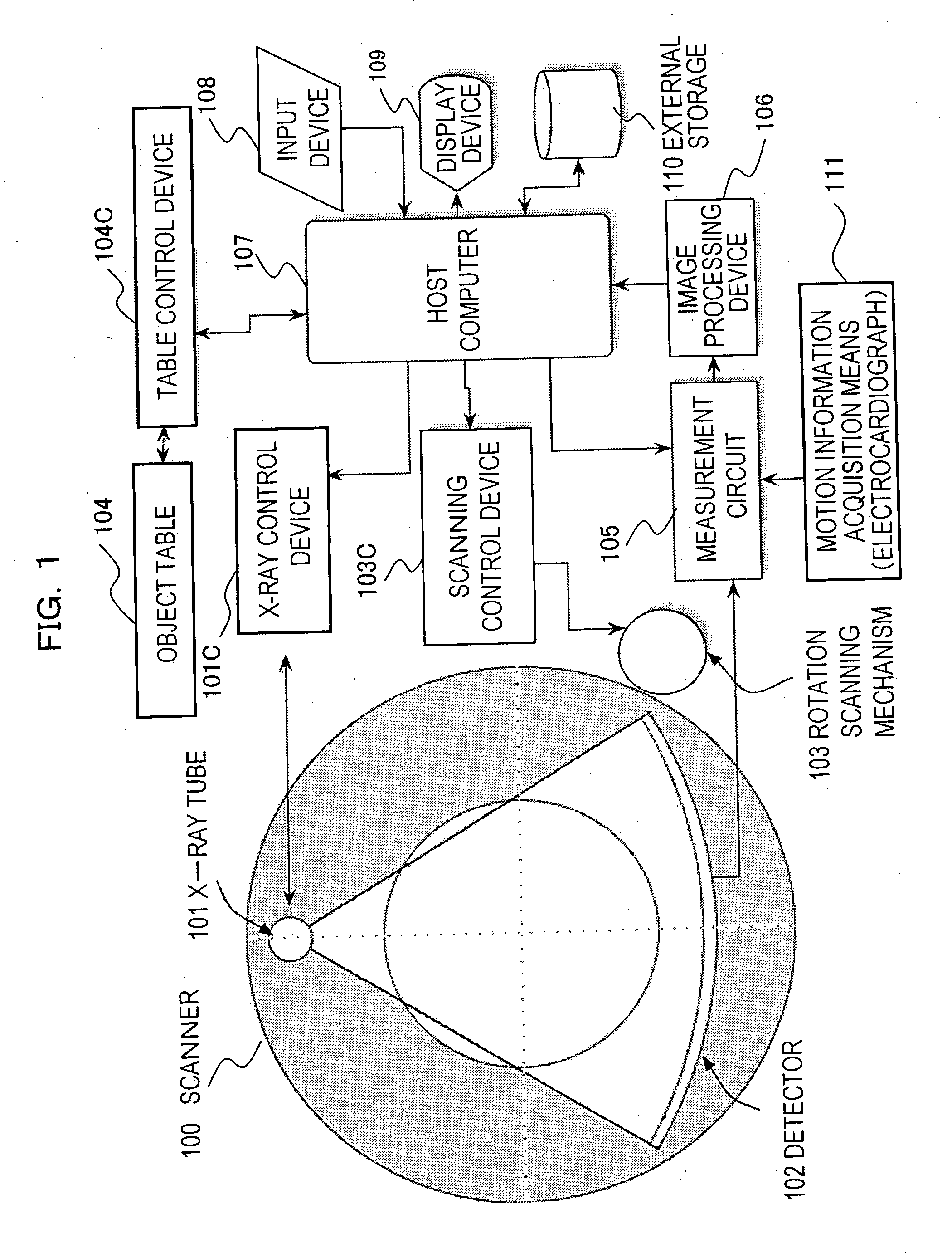
[0033] As shown in FIG. 1, the X-ray CT apparatus includes a host computer 107 that collectively controls the entire system, an X-ray generation system including an X-ray tube 101, a (rotation) scanning mechanism 103 disposed with a detection system including a detector 102, a conveyance-use patient table 104 at the time of patient position determination and helical scanning, an image processing device 106 that implements various kinds of image processing, an external storage device 110, a display device 109, and an input device 108 for an operator to input instruction information. The X-ray CT apparatus is configured so that motion information can be inputted from external motion information acquisition means 111. The motion information is, for example, periodical motion information, and is inputted from the motion information acquisition means 111 to a measurement circuit 105. When projection data per collection region are inputted from the detector 102, the motion information is ...

embodiment 2

[0050] In a second embodiment, similar to the first embodiment, the X-ray CT apparatus configuration shown in FIG. 1 is used. Here, description will be given using the heart as the motion portion.

[0051] First, portions that are the same as those in- the prior art will be described. The X-ray CT apparatus ordinarily has the configuration shown in FIG. 1. The X-ray tube 101 and the detector 102 are disposed opposing each other on the scanner 100 with the object sandwiched therebetween, the heart region of the object is irradiated with X-rays from an X-ray source while using a collimator to limit the region irradiated with the X-rays, the X-rays passing through the heart region of the object are detected with the detector 102, an electrocardiograph is attached to the object as the motion information acquisition means 111, and projection data of the heart region in the vicinity of the R wave is obtained while incorporating electrocardiograph information as information of the motion por...


PUM


Abstract

An X-ray CT apparatus comprises: motion information acquisition means that acquires periodical motion information on a motion portion of an object to be examined; a detector that rotates together with an X-ray source and detects X-rays applied to the object from the X-ray source to acquire projection data per collection region; and reconstruction means that processes the projection data resulting from the detector to reconstruct a tomogram of the object, wherein the X-ray CT apparatus further includes delay time determination means that determines a delay time by adding a time width of the collection region and a processing delay time in the X-ray CT apparatus and a time interval from the moment when the phase of the measured periodical motion information is matched with the phase of the rotation period of the X-ray CT apparatus to the moment when they are matched next time, and collection means that correlates, with the periodical motion information obtained by the motion information acquisition means, and successively collects the projection data obtained from the detector, with the reconstruction means starting reconstruction of the tomogram after the delay time.

Description

TECHNICAL FIELD [0001] The present invention relates to technology that enables a reduction in exposure, an improvement in image quality, and an increase in the processing speed of imaging when imaging a moving portion such as a heart, without lowering the diagnostic value of an X-ray CT apparatus. BACKGROUND ART [0002] It is known that when scanning and reconstruction are not done following the beat of the heart in heart region imaging, a pseudo-image called a motion artifact and blurring occur, which is unsuitable for clinical diagnosis. It is conceivable to hasten as much as possible the scanning speed as one approach to solve this problem, and there is a CT apparatus that uses an electron beam to realize this. This CT apparatus has a scanning speed of about 100 ms and is capable of tomography that is as sharp as if the heart had stopped. However, the cost of this CT apparatus using an electron beam is high, the CT apparatus is large, it is necessary to dispose the CT apparatus i...

Claims


Application Information

Patent Timeline
IPC IPC(8): A61B6/00G01N23/00G21K1/12H05G1/60A61B6/03
CPCA61B6/032A61B6/5288A61B6/542A61B6/027
Inventor MIYAZAKI, OSAMUNAKAZAWA, TETSUOKOKUBUN, HIROTO
Owner FUJIFILM HEALTHCARE CORP
Why Eureka
Try Eureka