
Method and system for assembling electroacoustic transducers

a technology of electroacoustic transducers and components, applied in the direction of transducer details, electric transducers, electrical apparatus, etc., can solve the problems of damage to the electromagnetic drive, and the process of assembling receivers of the kind used in listening devices has been very tedious and time-consuming

Inactive Publication Date: 2006-06-29
SONION NEDERLAND
View PDF5 Cites 21 Cited by
  • Summary
  • Abstract
  • Description
  • Claims
  • Application Information

AI Technical Summary

Benefits of technology

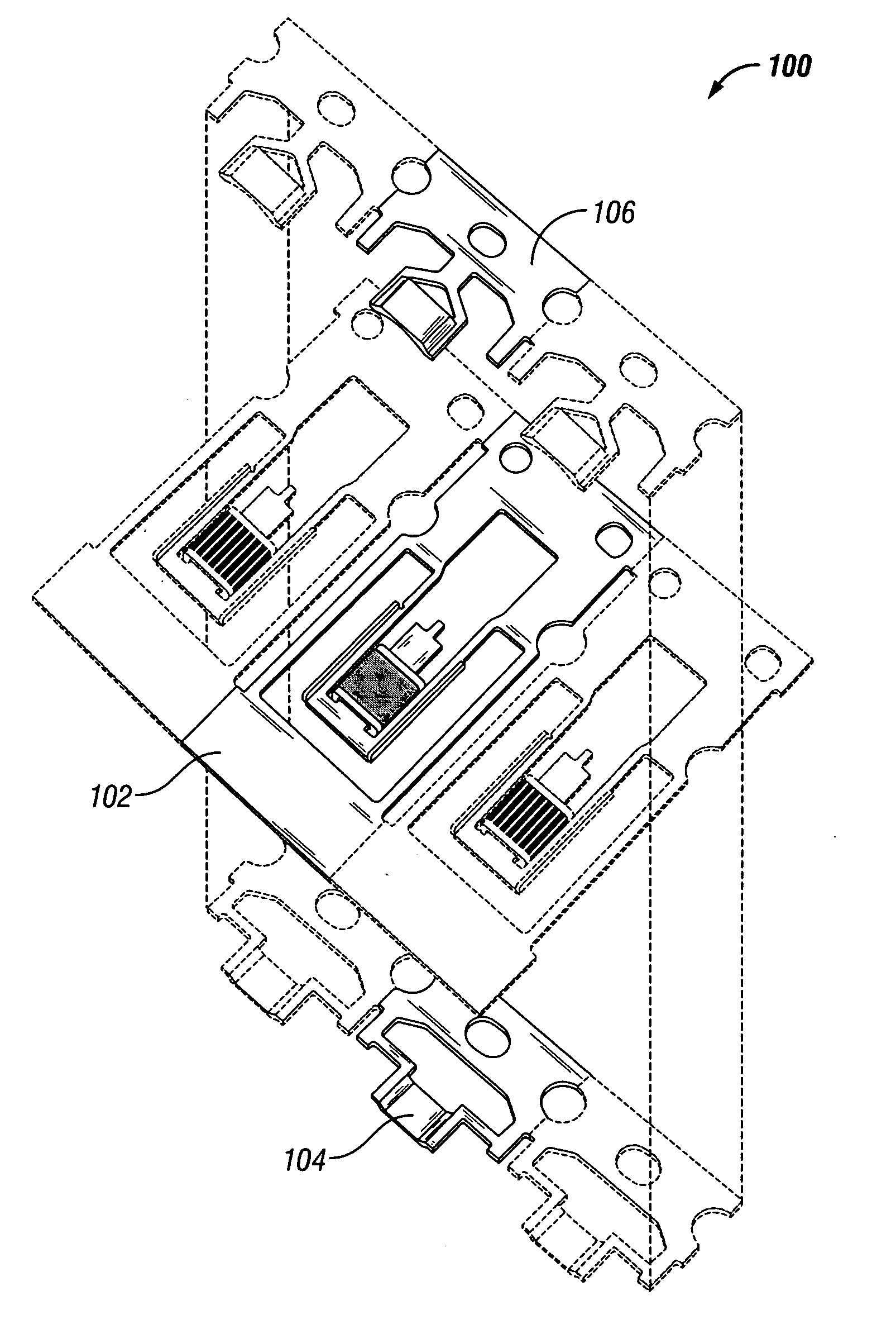
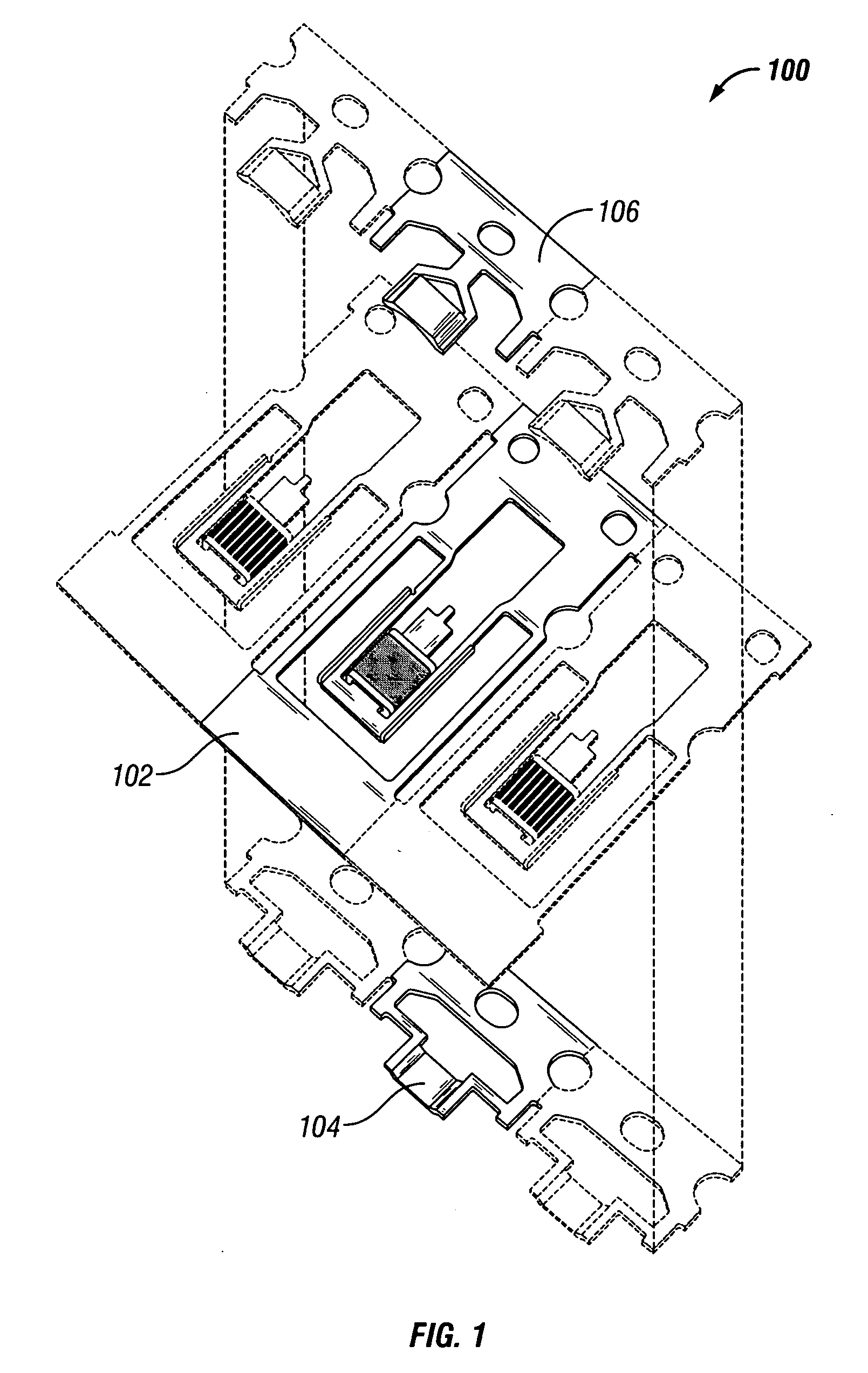
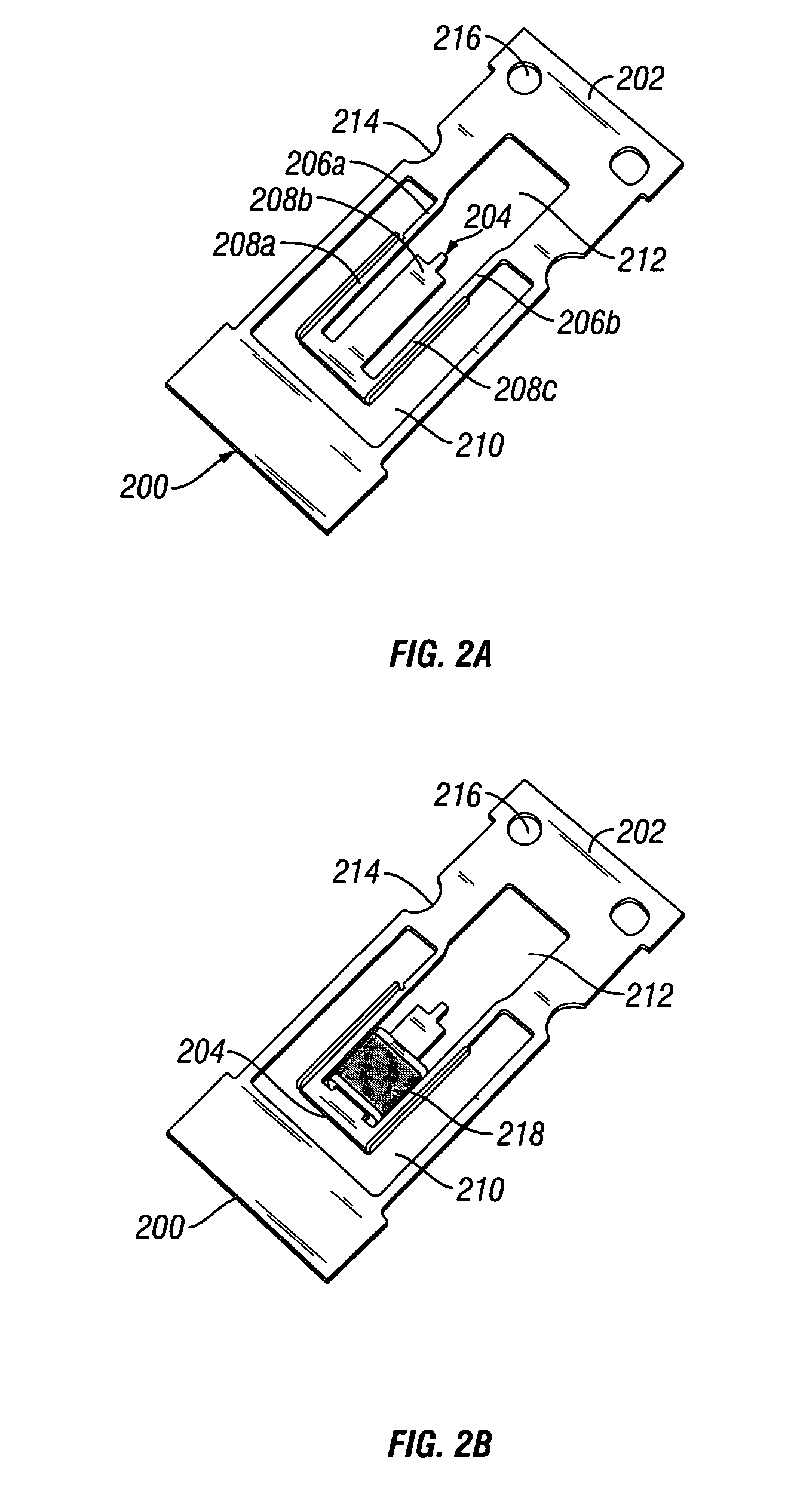
[0007] The present invention is directed to a method and system for facilitating automatic assembly of electroacoustic transducers for listening devices, such as hearing aids. The method and system of the invention provide the components of the electroacoustic transducer in the form of carriers. Each carrier includes a frame surrounding a preformed component. The preformed component is attached to the frame by at least one strut that holds the component in a fixed position within the frame. The frame may then be used as a guide or reference for mounting other components (whether provided on component carriers or not) to the preformed component. Some components, instead of being in a carrier, may be preassembled as a subassembly and then mounted to other components that are in a carrier. Several carriers may be connected sequentially in a strip and run through an assembly line to facilitate automatic assembly of multiple electroacoustic transducers in parallel.
[0013] In some embodiments, the electromagnetic drive assembly further comprises a lower magnet shell mounted on the armature, the lower magnet shell having exposed cutting surfaces indicative of removal of struts previously attached to the lower magnet shell. The electromagnetic drive assembly may further comprise an upper magnet shell mounted on the armature, the upper magnet shell having exposed cutting surfaces indicative of removal of struts previously attached to the upper magnet shell. The housing may have a size and shape that allows the receiver to be used in miniature listening devices, including hearing aids.

Problems solved by technology

An improperly positioned armature can damage the electromagnetic drive due to the deflections in the moving part of the armature.
As a result, the process of assembling receivers of the kind used in listening devices has heretofore been very tedious and time-consuming.

Method used


Image

  • Method and system for assembling electroacoustic transducers
  • Method and system for assembling electroacoustic transducers
  • Method and system for assembling electroacoustic transducers

Examples


Embodiment Construction

[0056] As mentioned above, embodiments of the invention use transducer components that are in the form of carriers. In one embodiment, the component carriers facilitate automatic assembly of electromagnetic drives, such as those used in the electroacoustic transducers of listening devices (e.g., hearing aids). In another embodiment, the component carriers facilitate automatic assembly of the housing that houses the electromagnetic drives. Both embodiments may be implemented independently of one another, or they may be implemented jointly. In either case, several component carriers may be connected together in series to form strips that are then run through an automated assembly line to construct the electromagnetic drives and / or housing. Although receivers are primarily described herein, those having ordinary skill in the art will recognize that the invention is equally applicable to assembly of microphones as well and to electroacoustic transducers in general.

[0057]FIG. 1 illustra...


PUM


Abstract

Method and system are disclosed for facilitating automatic assembly of electroacoustic transducers for listening devices, such as hearing aids. The method and system provide the components of the electroacoustic transducer in the form of carriers. Each carrier includes a frame surrounding a preformed component. The preformed component is attached to the frame by at least one strut that holds the component in a fixed position within the frame. The frame may then be used as a guide or reference for mounting other components (whether provided on component carriers or not) to the preformed component. Some components, instead of being in a carrier, may be preassembled as a subassembly and then mounted to other components that are in a carrier. Several carriers may be connected sequentially in a strip and run through an assembly line to facilitate automatic assembly of multiple electroacoustic transducers in parallel.

Description

FIELD OF THE INVENTION [0001] The present invention relates to miniature electroacoustic transducers used in listening devices, such as hearing aids. In particular, the present invention relates to a method and system for assembling such miniature electroacoustic transducers. BACKGROUND OF THE INVENTION [0002] A conventional listening device such as a hearing aid includes, among other things, a microphone and a receiver (generally referred to as electroacoustic transducers). The microphone collects sound waves and converts the sound waves to an electrical signal. The electrical signal is then processed (e.g., amplified) and provided to the receiver. The receiver converts the processed electrical signal into an acoustic signal and subsequently broadcasts the acoustic signal to the eardrum. [0003] A typical receiver includes, among other things, a housing that protects the sensitive components inside the receiver. The housing is of a sufficiently small size and shape that allows the r...

Claims


Application Information

Patent Timeline
Patent Type & Authority Applications(United States)
IPC IPC(8): H04R9/06
CPCH04R11/02H04R25/00H04R31/006
Inventor DE MOEL, JEROEN ANTHONIUSHIJMAN, JANBORCH TOT VERWOLDE, PHILIP LODEWIJK PIETER BARON VAN DERVAN BANNING, STEPHAN OLIVIER
Owner SONION NEDERLAND
Learn More