Power terminal and a unit comprising such power terminal

a power terminal and power supply technology, applied in the direction of fixed connections, basic electric elements, electrical apparatus, etc., can solve the problems of poor cooling of the terminal, expensive bends, soldering problems, etc., and achieve the effect of flexible new design, efficient use of circuit board area, and convenient mounting

Inactive Publication Date: 2006-06-29
DANAHER MOTION STOCKHOLM AB
View PDF9 Cites 15 Cited by
  • Summary
  • Abstract
  • Description
  • Claims
  • Application Information

AI Technical Summary

Benefits of technology

[0007] An object of the present invention is to provide a power terminal which is easy to mount, flexible in new designs and which makes efficient use of circuit board area.
[0009] Yet another object is to provide a power terminal which is cheap and easy to cast and surface treat.
[0010] A further object is to provide a power terminal with low demands on surrounding tolerances combined with good water protection.
[0011] The invention is based on the realization that a crank shaped power terminal having a main body and an eccentric body integral thereto, wherein a space is provided at the bottom of the power terminal adjacent to the eccentric body, provides a means for securing the terminal in an easy and efficient way while also providing for mounting of a current measurement device.

Problems solved by technology

Both solutions give a complicated assembly with many screws, often in inconvenient directions, and they also make the cooling of the terminal worse because of the high thermal resistance to the heat sink.
Furthermore these solutions make the cover and the control board tightly tied together and the terminal position cannot be moved on the cover without modifying the one on the control board and vice versa.
One problem here is to achieve a good sealing through the cover combined with robustness and ease of assembly.
The use of flat plates often require soldering fixtures in production to keep the bus bars upright, and there can be soldering problems if the boards are slightly bent.
To avoid mechanical forces from the outside going all the way down to the solder joints on the board you may want to insert some bends in the plate, but bends are costly because they are often made manually.
However, O-ring gaskets that are not rolling often have to be lubricated when mounted into the cover.
That is an extra cost and also an extra risk that the lubricant, which often contains oil is misplaced on the surface where the cable shoe is pressed to the terminal with the risk of a bad electrical connection.
Also, gaskets that are not rolling cannot be compressed that much because of the risk that they will get stuck, and they therefore have to be made of harder rubber that demands tighter tolerances on terminal and cover.

Method used


Image

  • Power terminal and a unit comprising such power terminal
  • Power terminal and a unit comprising such power terminal
  • Power terminal and a unit comprising such power terminal

Examples


Embodiment Construction

[0026] In the following a detailed description of preferred embodiments of the present invention will be given.

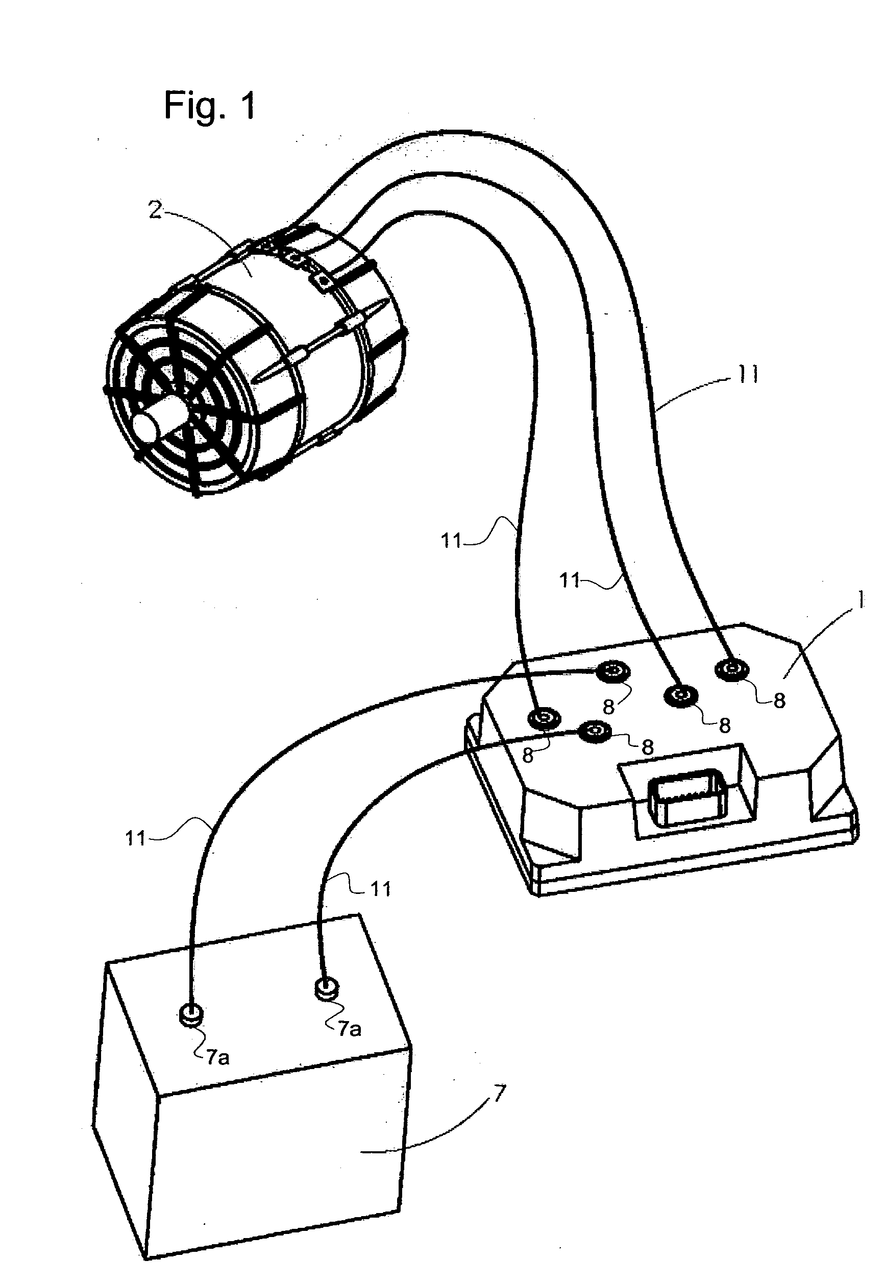
[0027] In FIG. 1, an overall view of a drive arrangement is shown. This arrangement includes a drive unit 1 connected to a battery 7 by means of two cables 11 connected to terminals 8, 7a on the drive unit and the battery, respectively. The drive unit is adapted for power control of an electric motor 2 and is connected thereto by means of three cables 11. These cables are, like the battery cables, connected to a respective power terminal 8 on the drive unit.

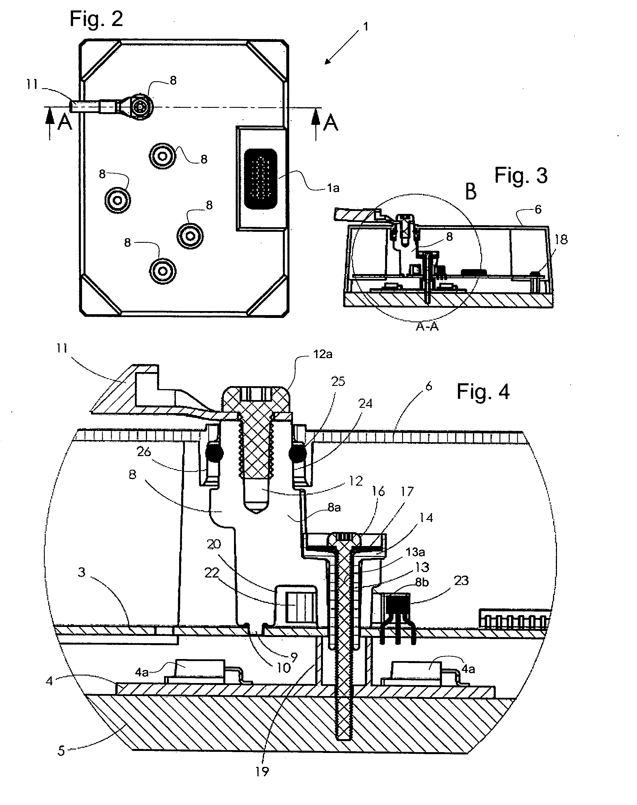
[0028] The power terminals appear more clearly in the plan view of FIG. 2. The cables 11, one of which is shown in FIG. 2, are attached to the power terminals 8 by means of a screw arrangement, as will be described in detail below. The drive unit 1 also has a pin connector 1a used for connecting the drive unit to a control computer, for example.

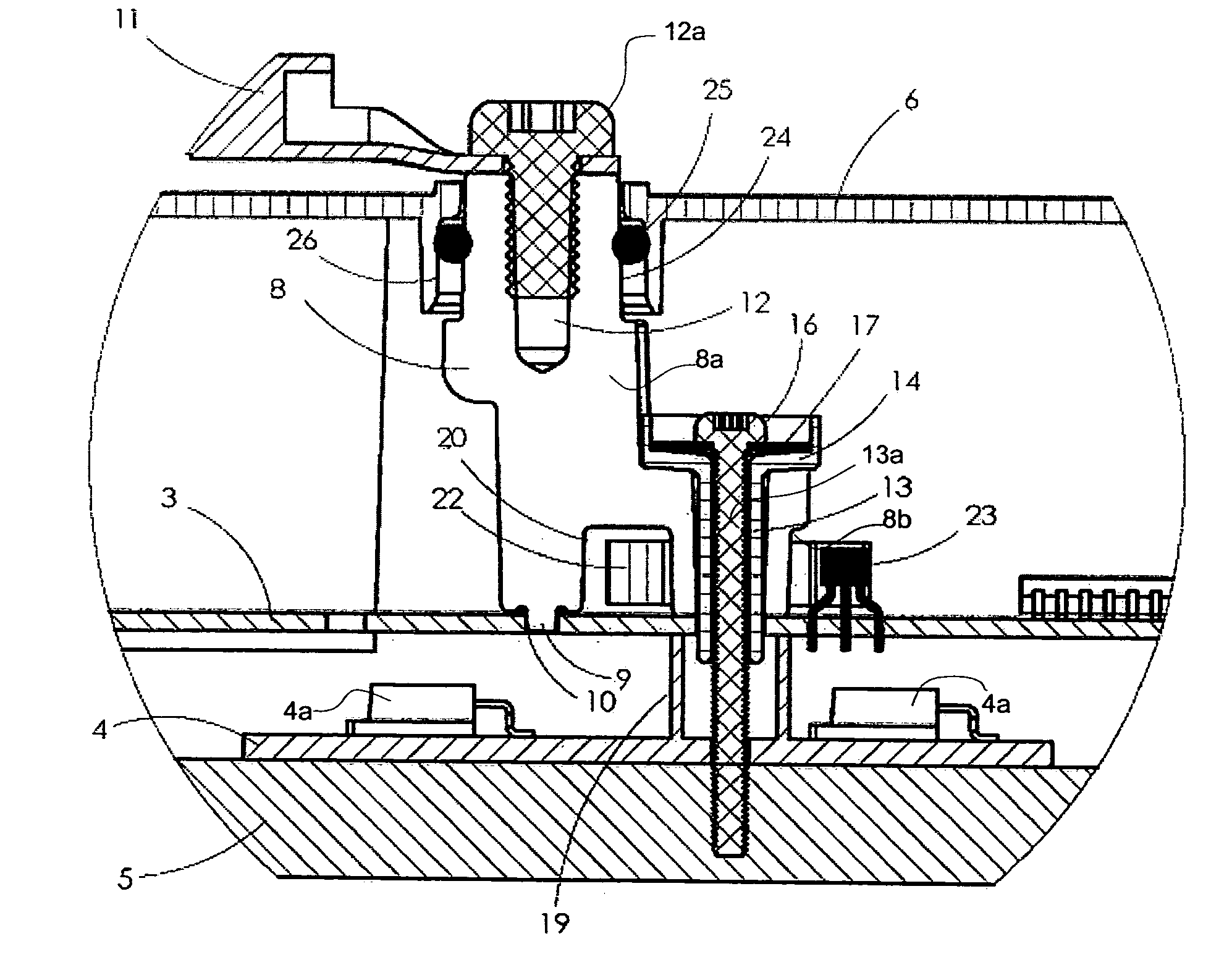
[0029] The interior of the drive unit 1 for power control of an electric m...


PUM


Abstract

A power terminal for electrical connection of an electric cable to a circuit board comprises a main body (8a) having a central longitudinal axis and means (12, 12a) for attaching a cable to the main body. An eccentric body (8b) integral with the main body (8a) and having a through hole (13) is arranged to receive a screw. A space (20) is provided at the bottom of the power terminal adjacent to the eccentric body. This configuration provides a means for securing the terminal in an easy and efficient way while also providing for mounting of a current measuring device, for example.

Description

FIELD OF INVENTION [0001] The present invention relates generally to power terminals and more particularly to a power terminal, particularly for electrical connection of an electric cable to a circuit board, which is easy to mount, flexible in new designs and which makes efficient use of circuit board area. A unit comprising such a power terminal is also provided. BACKGROUND [0002] Power terminals are used on devices such as drive units for electric motors. A conventional power terminal tower in a drive unit is often split in two halves where one goes up to the cover and one goes down to the power board and the halves are not on top of each other. Since the electrical signal in the terminal is used on both a control board and a power board both halves are mounted to the control board, which takes up a lot of space on the board, or one of the halves is placed outside of the board and is connected via a bus bar (normally a copper plate) which gives a more expensive solution and a bigg...

Claims


Application Information

Patent Timeline
Patent Type & Authority Applications(United States)
IPC IPC(8): H05K1/00H01R12/55
CPCH01R12/515
Inventor BERGLUND, JAN ANDERSKARLSSON, ULF BENGT INGEMAR
Owner DANAHER MOTION STOCKHOLM AB
Why Eureka
Try Eureka