Socket for led light source and lighting system using the socket
- Summary
- Abstract
- Description
- Claims
- Application Information
AI Technical Summary
Benefits of technology
Problems solved by technology
Method used
Image
Examples
first embodiment
1. FIRST EMBODIMENT
1.1 Construction of the Socket for LED Light Source
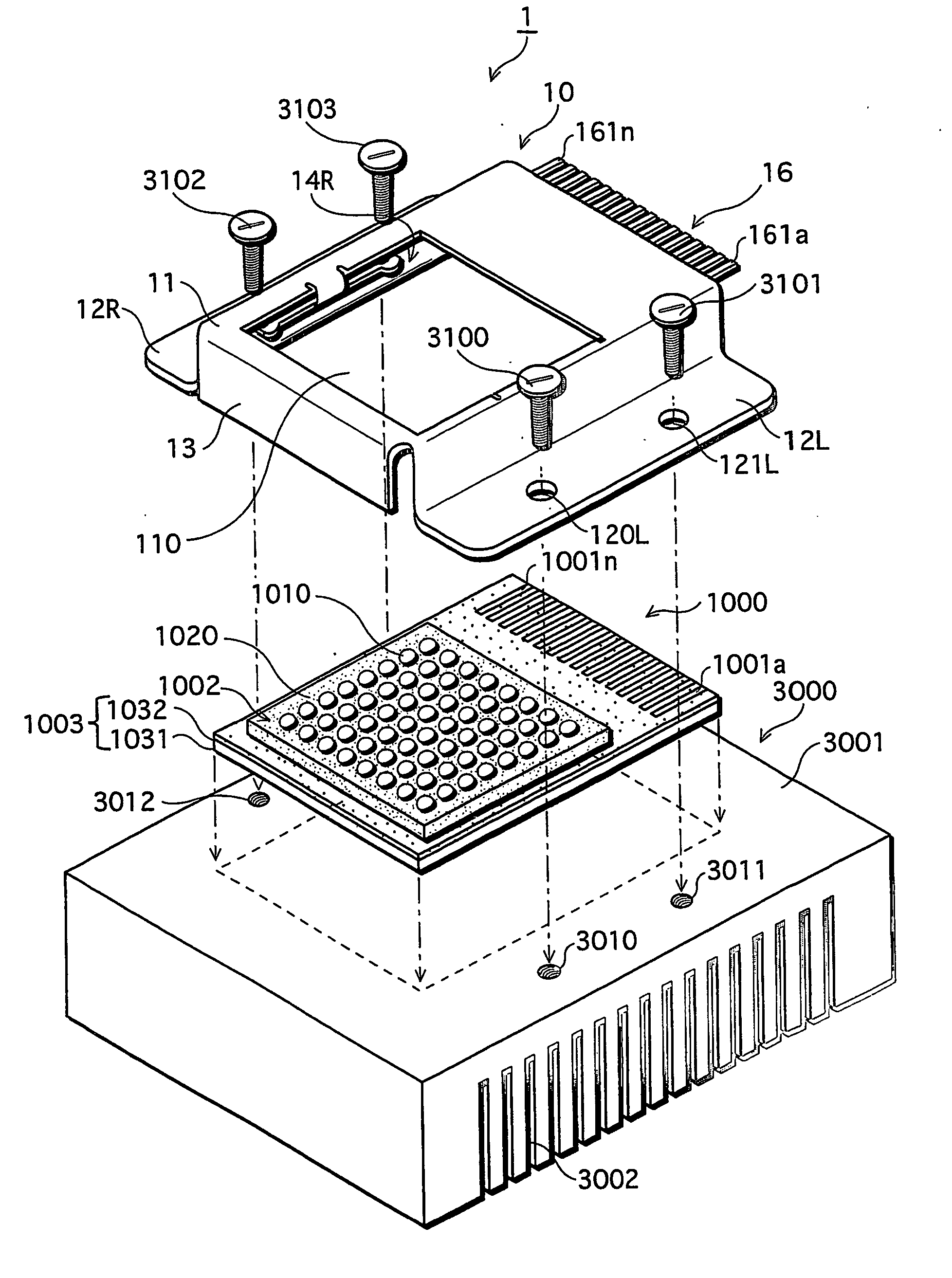
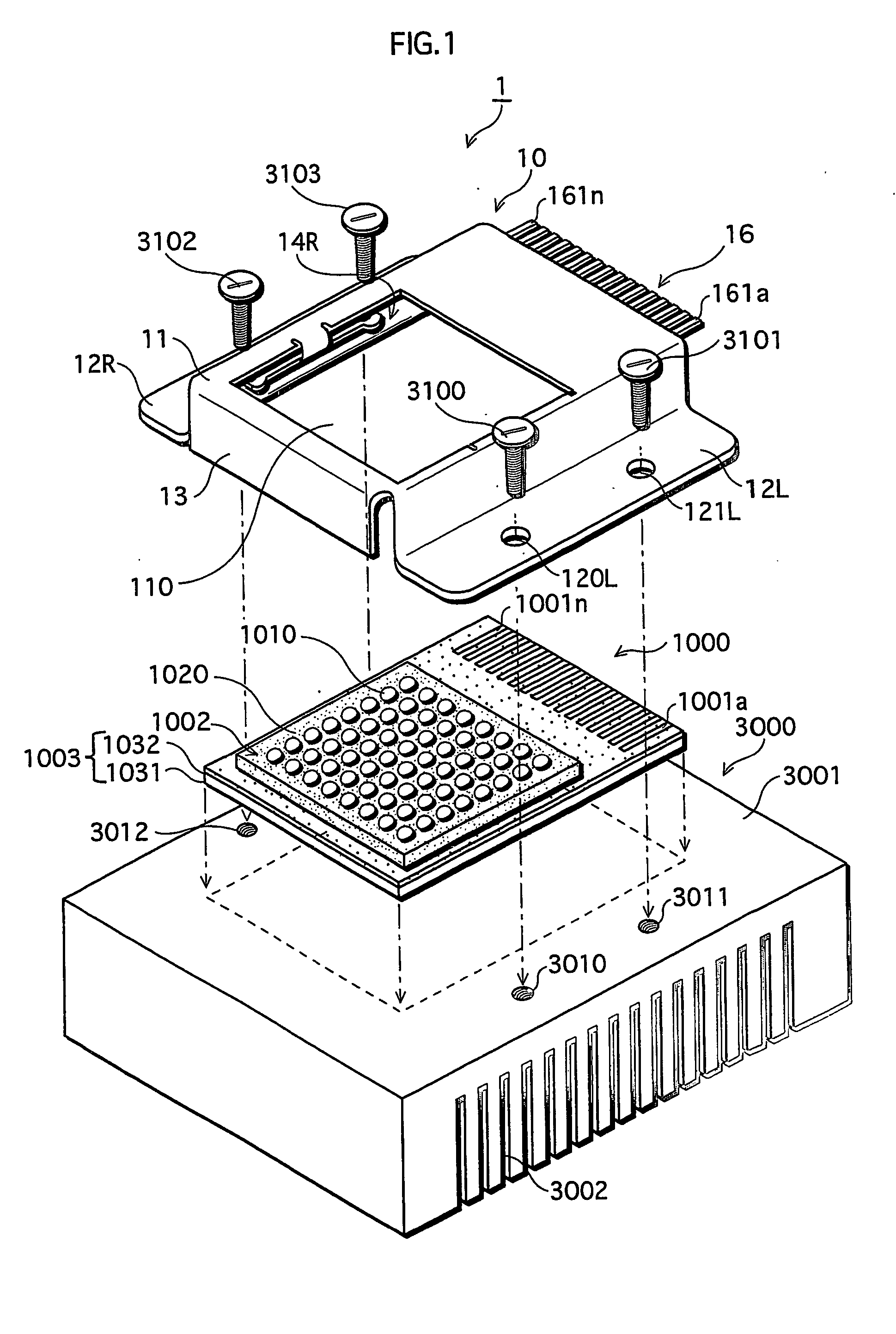
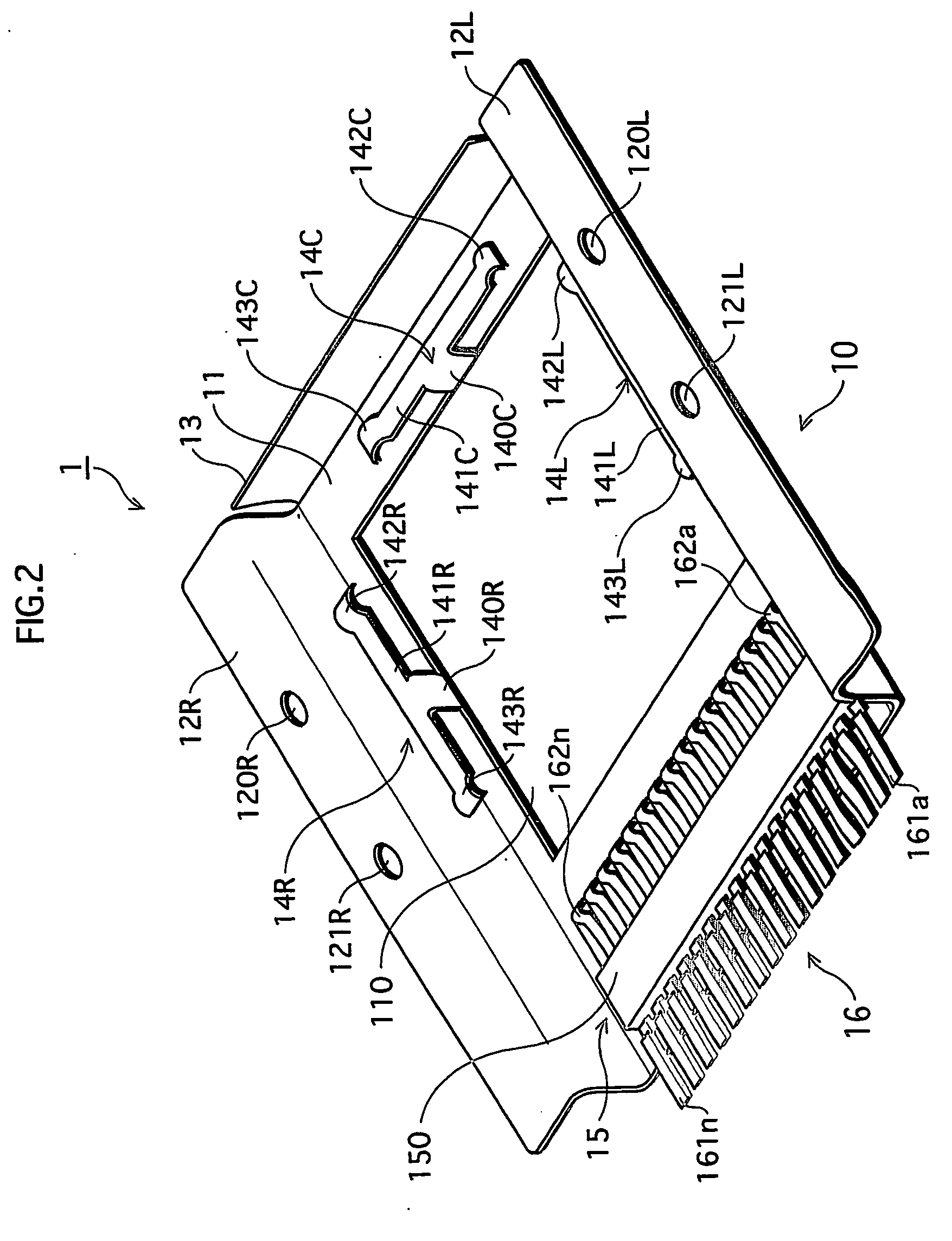
[0062]FIG. 1 shows the construction of a socket 1 designed for an LED light source, relating to a first embodiment of the present invention. FIG. 2 shows the construction of a back side of the socket 1. FIGS. 15A to 15C show the construction of an LED card.
[0063]FIG. 1 shows the constructions of the socket 1 designed for an LED light source, a card-type LED module 1000 as one example of the LED light source (hereafter simply “LED card 1000”), and a heat sink 3000.
[0064] As shown in the figure, the heat sink 3000 is made from a rectangular solid metal member (here, aluminum member) with good heat-releasing properties. In one main surface of the heat sink 3000, a large number of fins 3002 are formed like the teeth of a comb, to enhance the heat-releasing effect. On another main surface 3001 of the heat sink 3000 (the upper surface in the figure), screw holes 3010 to 3013 (3013 not shown) for screws 3100 to 3103 ...
second embodiment
2. SECOND EMBODIMENT
[0076]FIG. 4 shows the construction of an LED light-source socket relating to a second embodiment of the present invention.
[0077] The socket 2 relating to the second embodiment shown in the figure is, as its characteristic, formed by processing an aluminum plate with high heat conductivity. The socket 2 has a construction where an external terminal unit 27 having the same construction as that in the first embodiment is attached to a frame member 21 in which an opening unit 201 is formed by punching or shaving off the corresponding part of the aluminum plate. The lower surface of the frame member 21 is subjected to such patterning to form steps that correspond to the shape of the LED card 1000, so that the LED card 1000 can be securely covered and held by the frame member 21. The second embodiment differs from the first embodiment in that the frame member 21 of the socket 2 presses the peripheral parts of the light source unit 1002. It should be noted here that a...
third embodiment
3. THIRD EMBODIMENT
[0079]FIG. 5 shows the construction of an LED light-source socket relating to a third embodiment of the present invention.
[0080] As shown in the figure, the shape of the socket of the present invention should not be limited to the rectangular shape employed in the first and second embodiments. The socket 3 relating to the third embodiment is composed of a circular frame member 31 in which an opening unit 301 is formed. Screw holes 301 to 303 are formed in the frame member 31.
[0081] The socket 3 having this construction relating to the third embodiment can produce substantially the same effect as the effect described in the second embodiment. To be specific, the LED card 1000 can be positioned right below the frame member 31. Using the screw holes 301 to 303 shown in the figure, the socket 3 in which the LED card 1000 is set can be fixed to the heat sink. Here, the light source unit 1002 of the LED card 1000 is exposed through the opening unit 201, with its perip...
PUM
 Abstract
Description
Claims
Application Information
 - R&D
- Intellectual Property
- Life Sciences
- Materials
- Tech Scout
- Unparalleled Data Quality
- Higher Quality Content
- 60% Fewer Hallucinations
Browse by: Latest US Patents, China's latest patents, Technical Efficacy Thesaurus, Application Domain, Technology Topic, Popular Technical Reports.
© 2025 PatSnap. All rights reserved.Legal|Privacy policy|Modern Slavery Act Transparency Statement|Sitemap|About US| Contact US: help@patsnap.com


