

Remote chamber methods for removing surface deposits
a technology of surface deposits and remote chambers, applied in the direction of coatings, chemical vapor deposition coatings, chemistry apparatus and processes, etc., can solve the problems of pecvd equipment manufacturers
- Summary
- Abstract
- Description
- Claims
- Application Information
AI Technical Summary
Benefits of technology
Problems solved by technology
Method used
Image

Examples
example 1
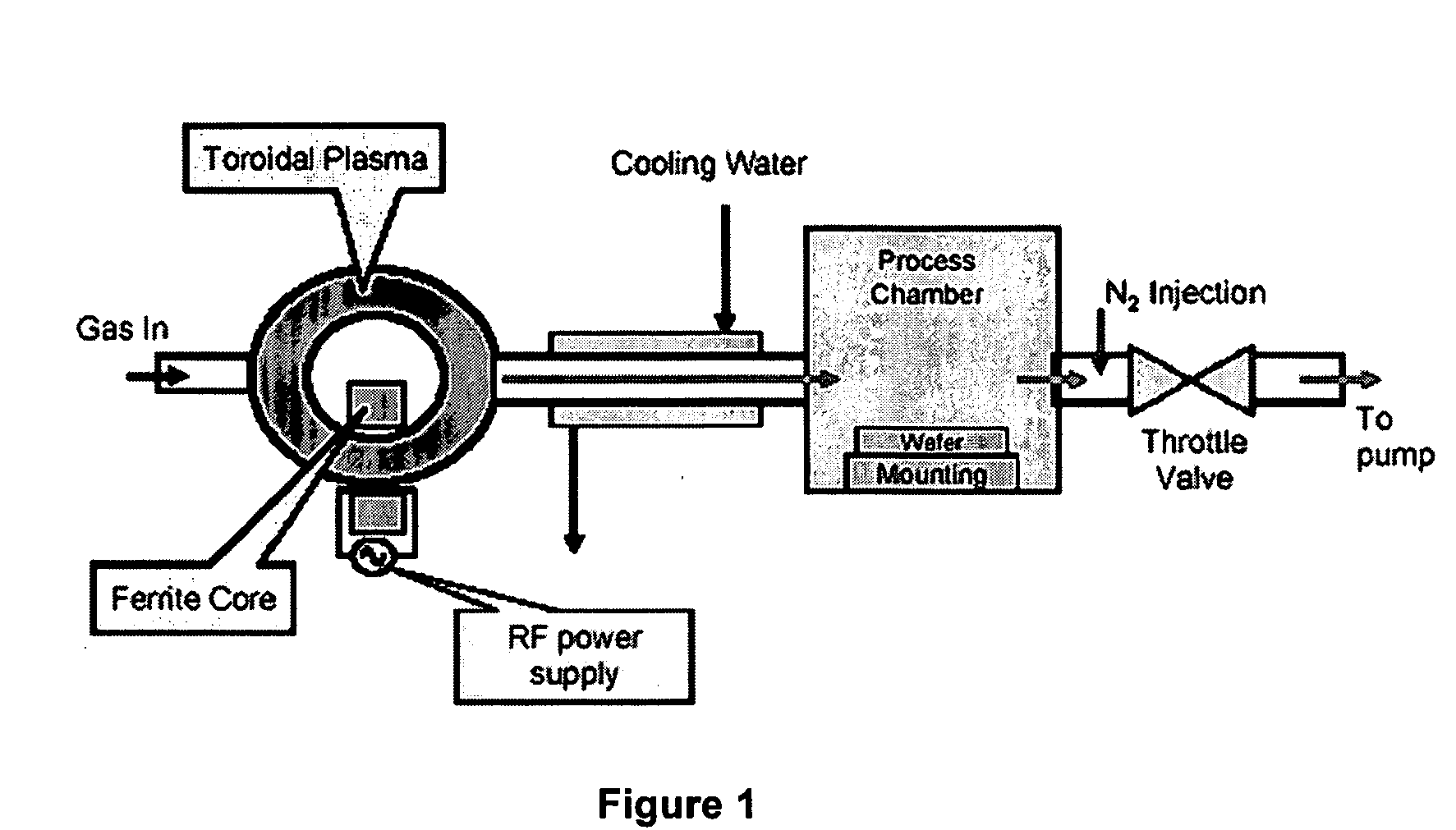
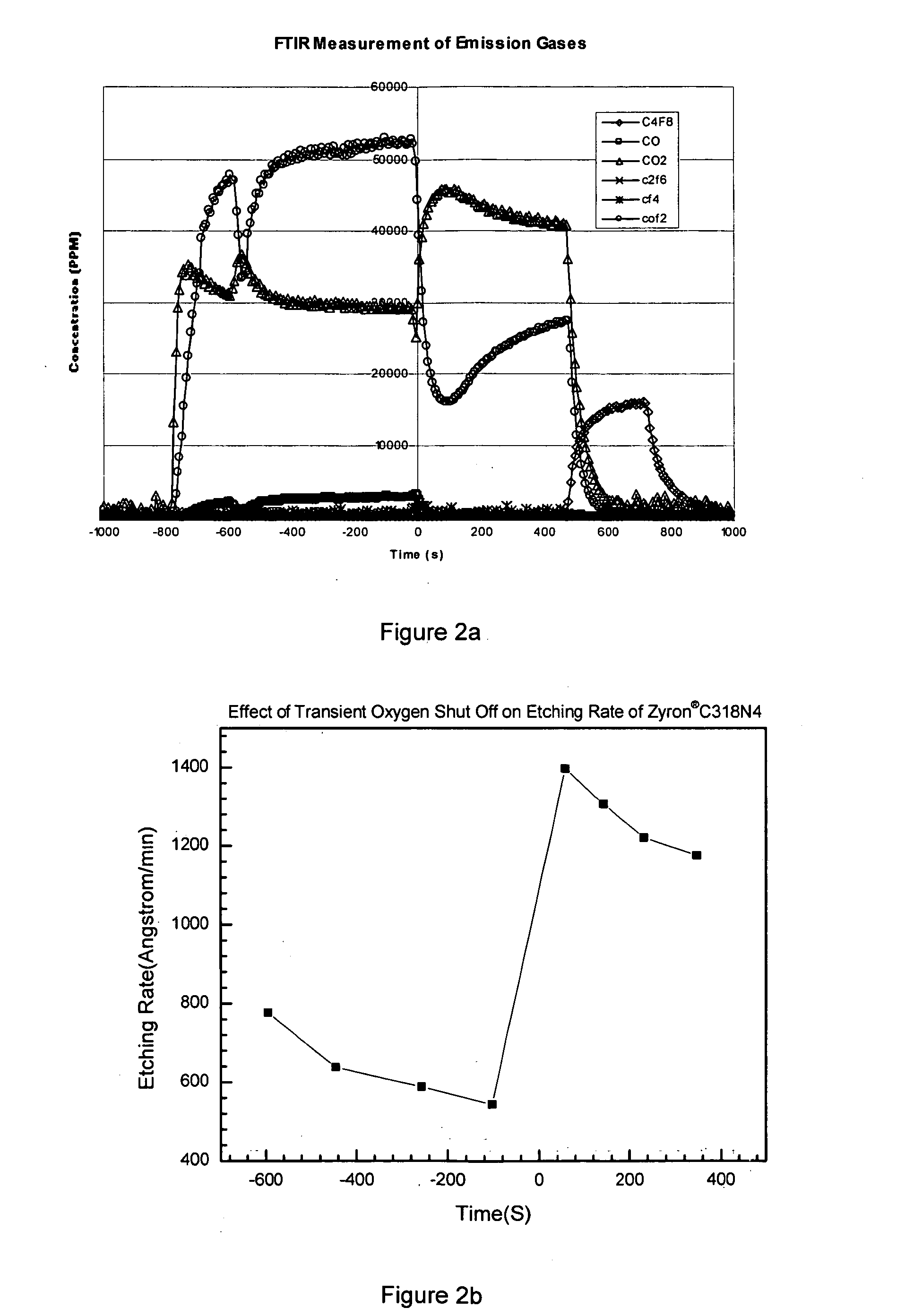
[0025] It was discovered that after certain periods of use, the etching rate of Zyron® C318N4 will drop to approximately one half of the previous rate. At the same time a much larger amount of COF2 in the effluent gases was observed. It was also found that rapid closing and opening of the oxygen valve for a period of a few seconds could increase the etching rate back to the previous level.
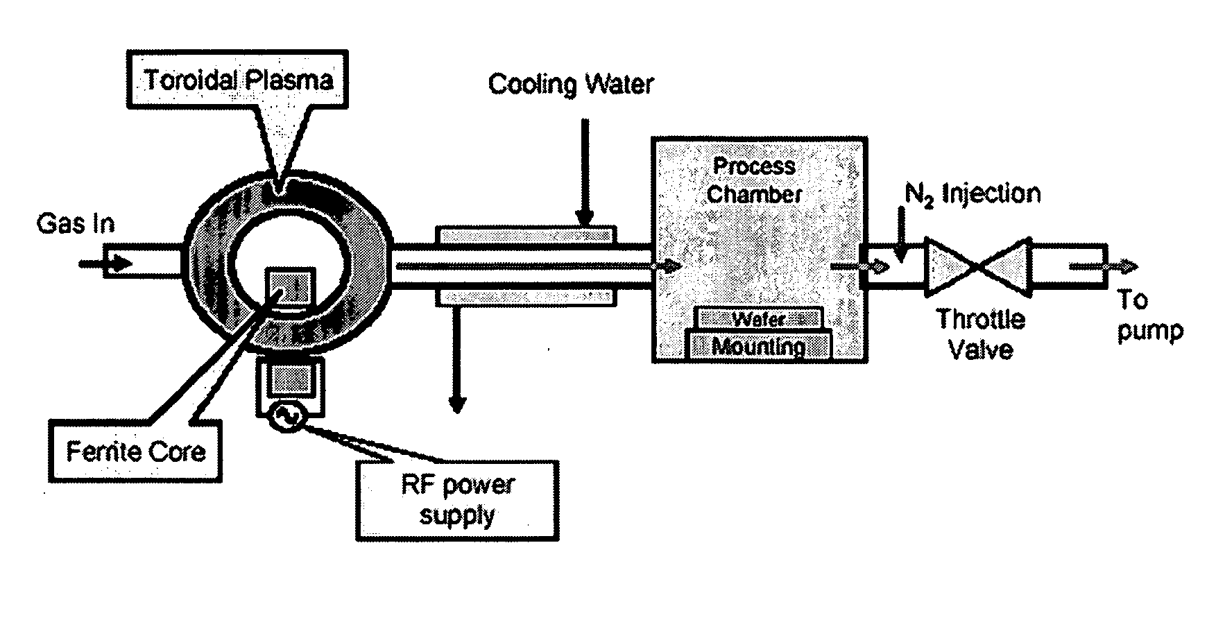
[0026] In this experiment, the feeding gas composed of O2, Zyron® C318N4 (C4F8) and Ar, wherein O2 flow rate is 1750 sccm, Ar flow rate is 2000 sccm, C4F8 flow rate is 250 sccm. Chamber pressure is 2 torr. The 400 KHz 8.9 KW RF power was turned on at −800 seconds and the feeding gas was activated to a neutral temperature estimated to be 5000 K. The activated gas then entered the process chamber and etched the SiO2 surface deposits on the mounting with the temperature controlled at 100° C. At the time of zero second, the oxygen valve was shut off for two seconds and then reopened. As a result of th...
example 2
[0027] This experiment was designed to measure the effect of the fluorocarbon rich plasma treatment on the interior surface of the apparatus. The etching rate was measured as 900 Angstrom / min according to the conditions described below before the fluorocarbon rich plasma treatment. The feeding gas composed of O2, Zyron® 8020 (C4F8) and Ar, wherein O2 flow rate is 1750 sccm, Ar flow rate is 2000 sccm, C4F8 flow rate is 250 sccm. Chamber pressure is 2 torr. The feeding gas was activated by 400 KHz 8.8 KW RF power to a neutral temperature of estimated to be 5000 K. The activated gas then passed through the heat exchanger connection, entered the process chamber and etched the SiO2 surface deposits on the mounting with the temperature controlled at 100° C.
[0028] Then the heat exchanger connection between the remote plasma source and the process chamber was treated by fluorocarbon rich plasma. The feeding gas mixture for the treatment consisted of 250 sccm Zyron® 8020 and 2000 sccm Ar. A...
example 3
[0030] This experiment was designed to measure the effect of the fluorocarbon rich plasma treatment on the interior surface of the apparatus. The etching rate was measured as 850 Angstrom / min according to the conditions described below before the fluorocarbon rich plasma treatment. The feeding gas composed of O2, C3F8 and Ar, wherein O2 flow rate is 1000 sccm, Ar flow rate is 2750 sccm, C3F8 flow rate is 250 sccm. Chamber pressure is 2 torr. The feeding gas was activated by 400 KHz 6.0 KW RF power to a neutral temperature of estimated to be 4500 K. The activated gas then passed through the heat exchanger connection, entered the process chamber and etched the SiO2 surface deposits on the mounting with the temperature controlled at 100° C.
[0031] Then the heat exchanger connection between the remote plasma source and the process chamber was treated by fluorocarbon rich plasma. The feeding gas mixture for the treatment consisted of 250 sccm C3F8 and 2750 sccm Ar. After activated by 400...
PUM
| Property | Measurement | Unit |
|---|---|---|
| temperature | aaaaa | aaaaa |
| temperatures | aaaaa | aaaaa |
| temperatures | aaaaa | aaaaa |
Abstract
Description
Claims
Application Information