Irrigation flushing system

a technology of irrigation system and flushing pipe, which is applied in the direction of spraying apparatus, botany apparatus and processes, horticulture, etc., can solve the problems of difficult flushing of low-pressure emitters, unsatisfactory cleaning solutions, and inability to flush pipes, so as to avoid undesirable spilling, reduce the effect of flow rate and low flow ra

Inactive Publication Date: 2006-07-06
NETAFIM LTD
View PDF8 Cites 48 Cited by
  • Summary
  • Abstract
  • Description
  • Claims
  • Application Information

AI Technical Summary

Benefits of technology

[0023] The method and the system for vacuum filling / flushing according to the present invention allow sparing use of the fluid (water, solution, disinfectant, etc.) and avoid undesirable spilling.
[0024] It will be appreciated that the method of the present invention can be used for filling or flushing any irrigation system, irrespective of its operative irrigation pressure, where the drippers have non-return valves. For example, some pressure-compensated drippers are designed to close at zero or negative pressure (vacuum). However, the above method and system for filling / flushing has special advantages for low-pressure drip irrigation pipes.
[0025] With the above method, one can use drippers which are not pressure-compensated but can irrigate under very low pressure, in order to have very low flow rate from the drippers. Such very low flow rates have certain agronomic advantages. Low flow rates make the drippers more sensitive to plugging, but since the drippers are not pressure-compensated, it is possible to raise the flow rate for a short period from time to time (daily, for example) by increasing the system inlet pressure, and thus flush the dirt out from the drippers.

Problems solved by technology

In this process, in an irrigation system equipped with dripping emitters, part of the cleaning solution is released through the emitters which may not always be desirable.
However, it is impossible to flush the pipes under pressure that is 2 m H2O or higher with closed drippers, and then use the same drippers for irrigation under pressure that is lower than 2 m H2O.
Low-pressure emitters are hard to flush as their operative pressure is low and may leak and damage the plants if higher pressure is used for flushing.

Method used


Image

  • Irrigation flushing system
  • Irrigation flushing system
  • Irrigation flushing system

Examples


Embodiment Construction

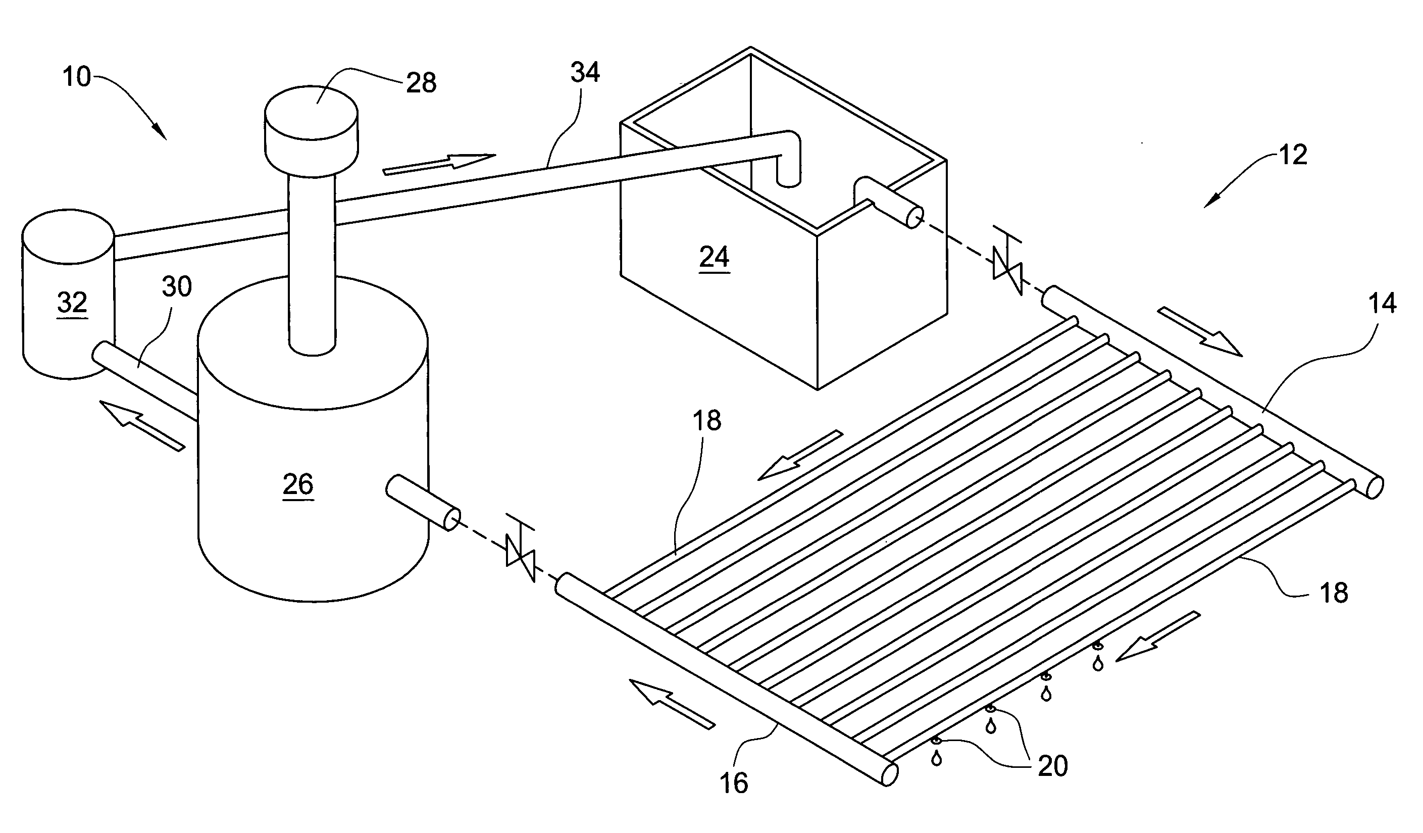
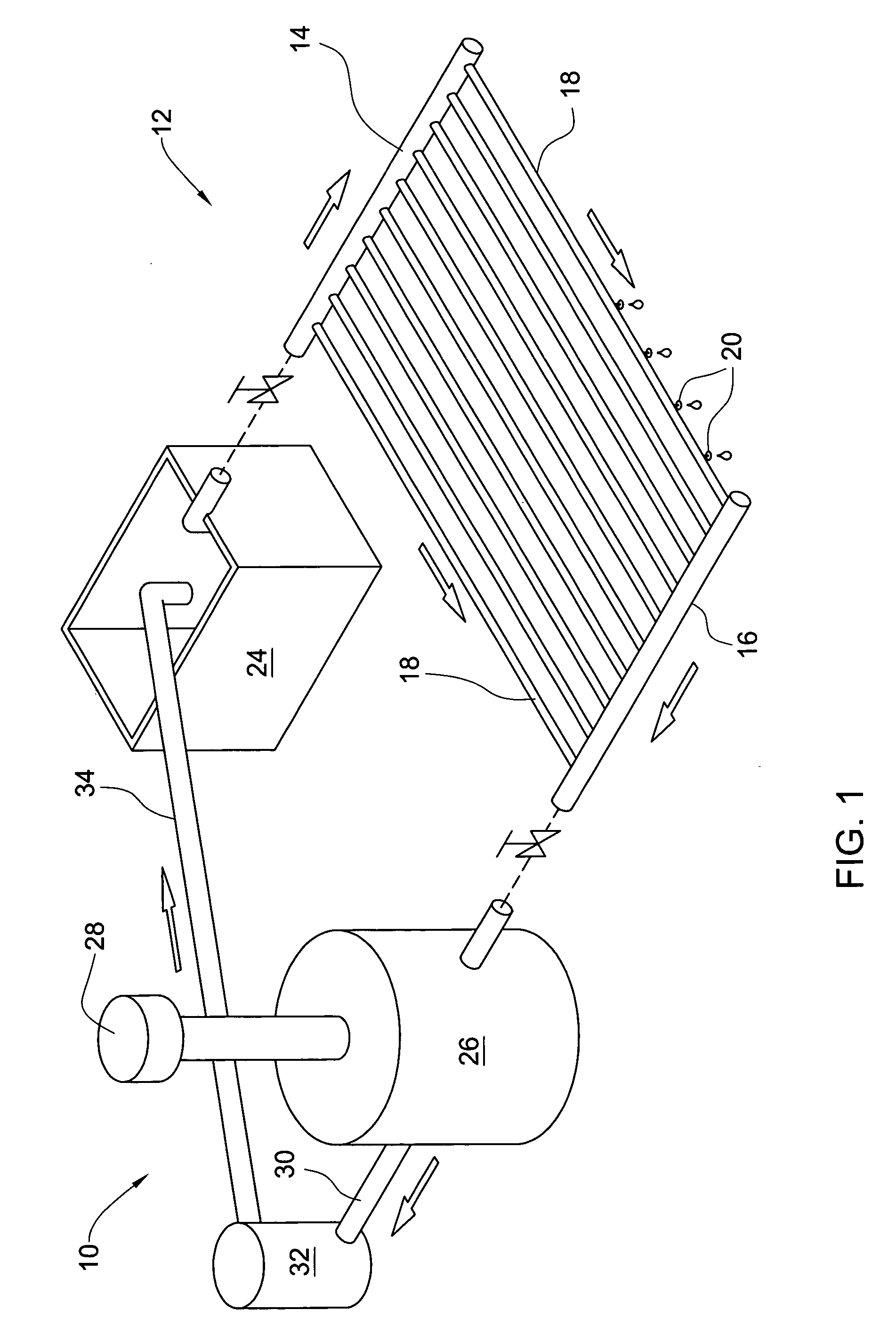
[0032] With reference to FIG. 1, there is shown schematically an arrangement 10 for vacuum-flushing a drip-irrigation system 12. The drip-irrigation system 12 comprises main water supply pipes 14 and 16, and a plurality of branch pipes 18 connected to the main pipes. The branch pipes 18 are equipped with drip emitters 20 having non-return valves (shown in detail below).

[0033] In normal irrigation operation, one or both main pipes 14 and 16 are connected to a pressurized source of irrigation water (not shown). The irrigation water flows under low operative pressure PO into the branch pipes 18 and leaves them through the drip emitters 20. The drip emitters 20 are open under zero or very low positive pressure so that the system 12 may perform irrigation under 20-30 cm H2O.

[0034] The flushing arrangement 10 includes a non-pressurized tank 24 for flushing solution, a vacuum tank 26 equipped with a vacuum pump 28, drain pipe 30, pressure pump 32 and a return pipe 34.

[0035] The solution...


PUM


Abstract

A method and a system for filling or passing a fluid through irrigation pipes equipped with dripping emitters having a non-return valve. The irrigation pipes are connected at one end to a container with the fluid and at the other end to an operable vacuum source such as vacuum pump. The vacuum source is operated to create vacuum in the pipes to suck the fluid from the container to fill the pipes. The fluid may be passed through the pipes to the vacuum source and then returned to the container by another pipe, or may be retained in the pipes without flow, or may be subjected to pressure pulses. In all cases, the non-return valves are plugged under the vacuum so as to prevent entry of external air or water into the pipes through the dripping emitters. A non pressure-compensated dripping emitter with built-in non-return valve is provided as well.

Description

FIELD OF THE INVENTION [0001] This invention relates to systems for flushing (cleaning) irrigation pipes, in particular to pipes equipped with low-pressure dripping emitters. BACKGROUND OF THE INVENTION [0002] Cleaning of irrigation pipes is conventionally made by flushing them with clean water or special solutions. A cleaning solution is pumped into one end of the irrigation pipe under pressure and removed from the other end. In this process, in an irrigation system equipped with dripping emitters, part of the cleaning solution is released through the emitters which may not always be desirable. To overcome the problem of solution being released from the dripping emitters, one normally uses dripping emitters that stay closed under some threshold pressure, the pipes being flushed under pressure below that threshold, so that the drippers are closed. The pressure that is necessary for flushing is usually about 2 m H2O or higher; therefore the drippers should open only above that pressu...

Claims


Application Information

Patent Timeline
Patent Type & Authority Applications(United States)
IPC IPC(8): B05B15/00
CPCA01G25/02
Inventor KEREN, RON
Owner NETAFIM LTD
Why Eureka
Try Eureka