
Liquid crystal display device

a liquid crystal display and display device technology, applied in static indicating devices, cathode-ray tube indicators, instruments, etc., can solve the problems of significant difference between the actual position and the displayed position of the moving object, and it is difficult to continuously display the positional variation of the moving object in almost real time, so as to reduce the phenomenon of tail trail

Inactive Publication Date: 2006-07-06
DENSO CORP
View PDF18 Cites 11 Cited by
  • Summary
  • Abstract
  • Description
  • Claims
  • Application Information

AI Technical Summary

Benefits of technology

[0007] It is an object of the present invention to provide a liquid crystal display device to decrease the above-described “tail trail” phenomenon and enable recognition of an almost actual position of a moving object.
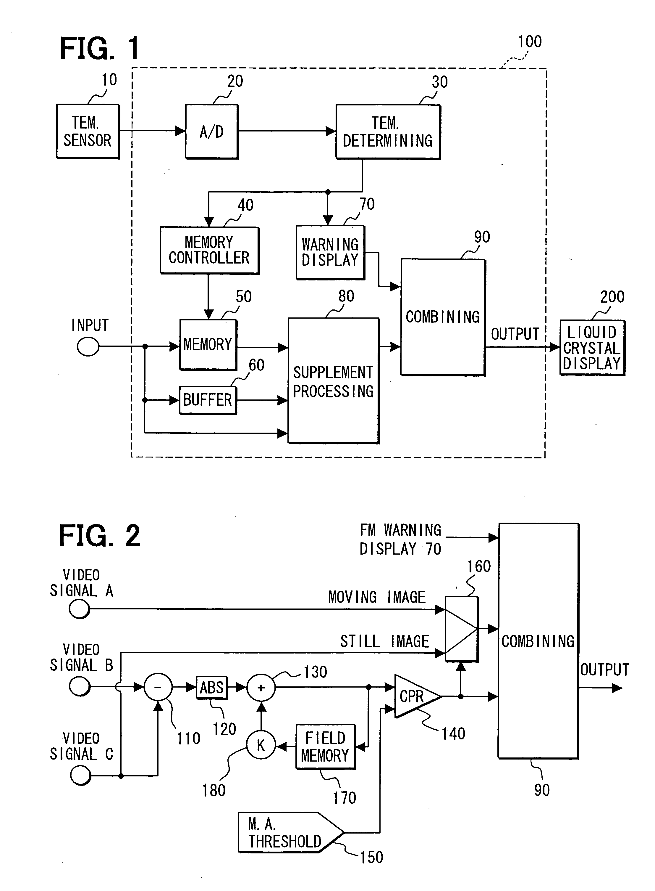
[0009] Under this structure of the present invention, when the temperature of the liquid crystal panel decreases less than a reference temperature (e.g., less than zero degree centigrade), video display data is generated for displaying the moving image portion by repeatedly using the same video signal by the set repetition times. This achieves an effect similar to that obtained when a field frequency decreases, thereby decreasing the “tail trail” phenomenon of the moving object.
[0010] Furthermore, the movement display data for indicating movement positions of the moving image portion is combined with the video display data. This movement display data does not show the moving image portion itself but shows a symbol indicating only a movement position of the moving object. Therefore, the “tail trail” phenomenon is not involved by the movement display data; thereby, the almost actual position of the moving object can be recognizably displayed.

Problems solved by technology

Therefore, when a video signal is for displaying the moving object, it may become difficult to continuously display positional variation of the moving object in almost real time.
This poses a problem that there is a significant difference between an actual position and a displayed position of the moving object on the liquid crystal panel.

Method used


Image

  • Liquid crystal display device
  • Liquid crystal display device
  • Liquid crystal display device

Examples


Embodiment Construction

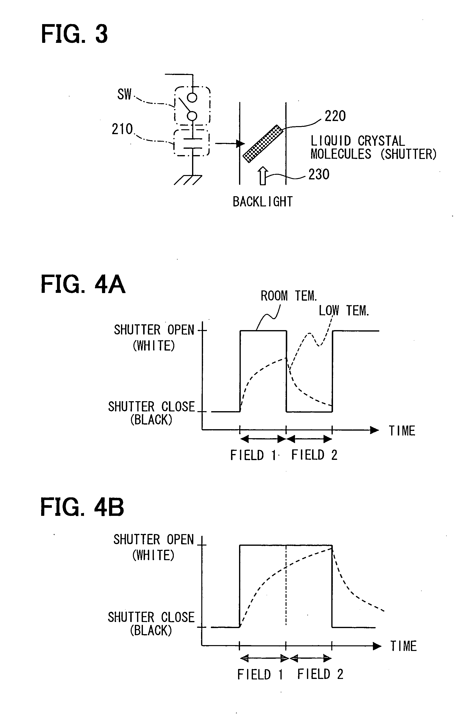
[0019] A liquid crystal display device according to an embodiment will be explained with reference to figures. The device is, for instance, applicable to a case where a camera shoots video surrounding a vehicle, e.g., forward, sideward, or rearward of a vehicle, and the video shot by the camera is displayed inside the vehicle. If this vehicle is located in a cold district whose outdoor temperature is below the freezing temperature, the response of the liquid crystal is slow and the “tail trail” phenomenon may thereby take place.

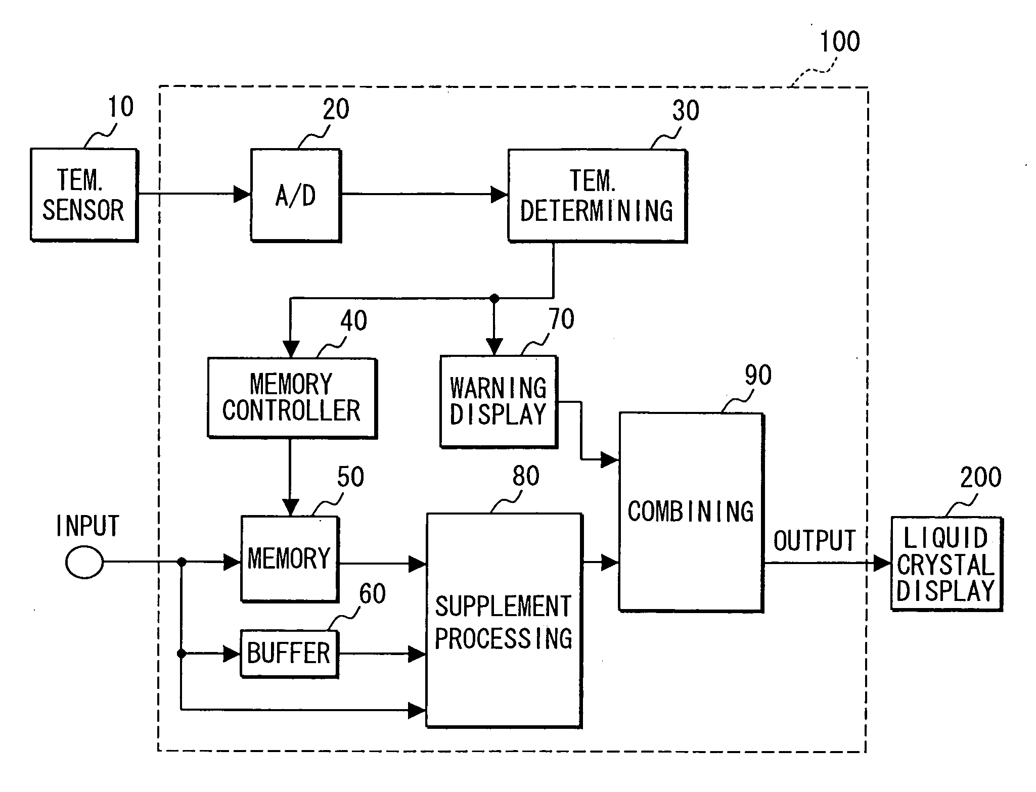
[0020] As shown in FIG. 1, the liquid crystal display device includes a liquid crystal monitor 200 as a displaying unit, a temperature sensor 10 as a temperature detecting unit such as a thermistor for detecting temperatures, and a control unit 100.

[0021] The temperature sensor 10 is, for instance, arranged in the front surface of a liquid crystal panel (or LCD panel) to continuously output analog signals corresponding to temperatures of the liquid crystal ...


PUM


Abstract

A moving image portion that indicates a moving object moving not less than a given movement amount and a still image portion other than the moving image portion are distinguished with respect to a video signal. Video display data for displaying the moving image portion is generated by repeatedly using the same video signal by repetition times based on temperature of a liquid crystal panel. Movement display data for displaying movement positions of the moving image portion is then generated based on a video signal obtained after the video signal used for displaying the moving image portion and is combined with the video display data. This achieves an effect similar to that obtained by decreasing a field frequency and decreases a “tail trail” phenomenon of the moving object. Furthermore, the movement display data enables recognition of the almost actual position of the moving object.

Description

CROSS REFERENCE TO RELATED APPLICATIONS [0001] This application is based on and incorporates herein by reference Japanese Patent Application No. 2005-1914 filed on Jan. 6, 2005. FIELD OF THE INVENTION [0002] The present invention relates to a liquid crystal display device. BACKGROUND OF THE INVENTION [0003] In a liquid crystal panel, viscosity of liquid increases at low temperatures. A response time period from when voltage is applied to liquid crystal molecules to when the liquid crystal molecules start moving becomes long at low temperatures. Consequently, when a moving image is displayed on a liquid crystal panel at low temperatures, as shown in FIGS. 6A, 6B, a moving object (A0, B0) is shown to trail (a so-called “tail trail” phenomenon takes place along a moving object image (AW, BW)). [0004] Patent Document 1 proposes a liquid crystal display device that changes a switching frequency of a video signal and backlight for displaying video based on temperature of the liquid crysta...

Claims


Application Information

Patent Timeline
IPC IPC(8): G09G3/36
CPCG09G3/3611G09G2320/0257G09G2320/0261G09G2320/041G09G2320/103G09G2340/12G09G2340/16G09G2360/18
Inventor NAGATA, MITSUTOSHI
Owner DENSO CORP
Learn More