Ntsc signal detector

a signal detector and receiver technology, applied in the field of communication systems, can solve the problem of design reliability above 10 db, and achieve the effect of reducing noise immunity and reducing the presence of interfering ntsc co-channel signals

Inactive Publication Date: 2006-07-06
THOMSON LICENSING SA
View PDF3 Cites 30 Cited by
  • Summary
  • Abstract
  • Description
  • Claims
  • Application Information

AI Technical Summary

Benefits of technology

[0007] In another embodiment of the invention, an NTSC detector includes at least a carrier tracking loop, peak detector, a D / U signal power ratio estimator and a horizontal synchronization (sync) detector. The carrier tracking loop provides a tracking signal representative of the possible presence of a video carrier of an interfering NTSC video signal while the peak detector provides peak data derived from the tracking signal to the D / U signal power ratio estimator. The latter provides, as a function of the peak data, an estimate of a D / U signal power ratio with respect to a desired ATSC co-channel signal. In addition, the horizontal sync detector provides a control signal, or sync detection signal, representative of the presence of an NTSC horizontal sync signal. The sync detection signal may be used by the receiver to further improve noise immunity during periods of the horizontal sync signal.
[0008] In accordance with the principles of the invention, the above-described NTSC detector can be used by a multimedia receiver, e.g., an ATSC / NTSC receiver, to select one of a number of receiver modes of operation. For example, if the multimedia receiver is attempting to recover data from a received ATSC signal and if the estimate of the D / U power signal ratio provided by the NTSC detector exceeds a predefined threshold, the multimedia receiver then switches in an ATSC comb filter, or similar, for processing of the received ATSC signal to mitigate the presence of an interfering NTSC co-channel signal. Another usage of the NTSC detector is to provide a positive indication to the tuning system of the multimedia receiver that the NTSC detected carrier is in fact the video rather than the aural carrier. A further usage of this NTSC detector is to provide phasing and prediction of the NTSC synchronization signals for providing intelligent noise blanking of the NTSC signal by the multimedia receiver when processing a received ATSC signal.

Problems solved by technology

Unfortunately, this design is not reliable for D / U ratios above 10 dB.

Method used


Image

  • Ntsc signal detector
  • Ntsc signal detector
  • Ntsc signal detector

Examples


Embodiment Construction

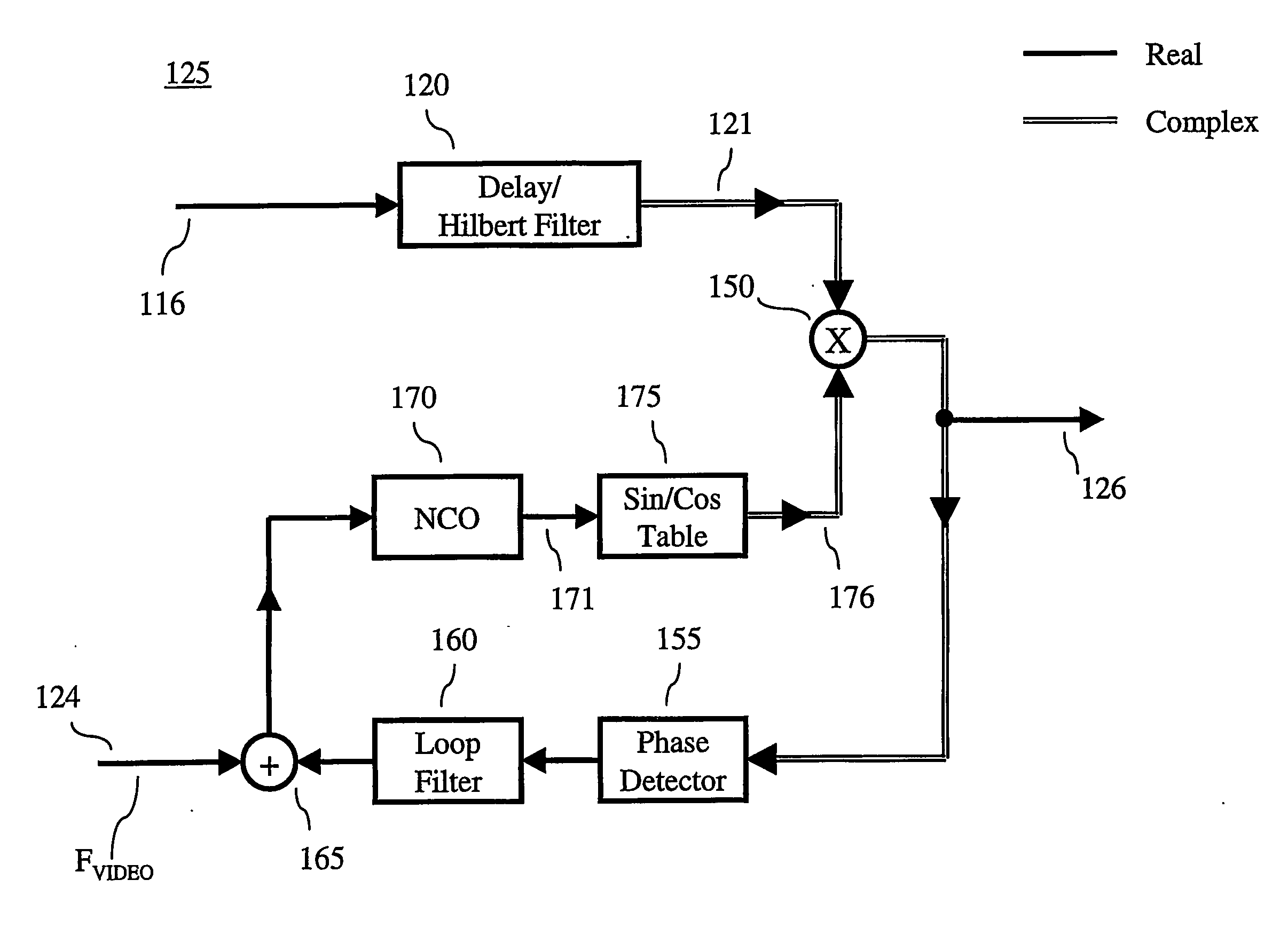
[0023] Other than the inventive concept, the elements shown in the figures are well known and will not be described in detail. For example, other than the inventive concept, a television, and the components thereof, such as a front-end, Hilbert filter, carrier tracking loop, video processor, remote control, etc., are well known and not described in detail herein. In addition, the inventive concept may be implemented using conventional programming techniques, which, as such, will not be described herein. Finally, like-numbers on the figures represent similar elements.

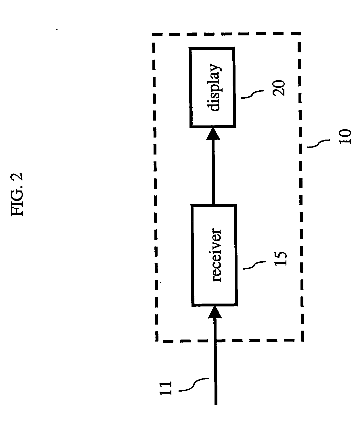
[0024] A high-level block diagram of an illustrative television set 10 in accordance with the principles of the invention is shown in FIG. 2. Television (TV) set 10 includes a receiver 15 and a display 20. Illustratively, receiver 15 is an ATSC-compatible receiver. It should be noted that receiver 15 may also be NTSC-compatible, i.e., have an NTSC mode of operation and an ATSC mode of operation such that TV set 10 is ca...


PUM


Abstract

An NTSC (National Television Systems Committee) co-channel interference detector includes at least a carrier tracking loop, peak detector and a D/U (Desired-to-Undesired) signal power ratio estimator. The carrier tracking loop provides a tracking signal representative of the possible presence of a video carrier of an interfering NTSC video signal while the peak detector provides peak data derived from the tracking signal to the D/U signal power ratio estimator. The latter provides, as a function of the peak data, an estimate of a D/U signal power ratio with respect to a desired ATSC (Advanced Television Systems Committee) co-channel signal.

Description

BACKGROUND OF THE INVENTION [0001] The present invention generally relates to communications systems and, more particularly, to an NTSC signal detector in a receiver. [0002] During the transition from analog to digital terrestrial television in the United States, both analog NTSC (National Television Systems Committee) based transmissions and digital ATSC-HDTV (Advanced Television Systems Committee-High Definition Television) based transmissions are expected to co-exist for a number of years. As such, an NTSC broadcast signal and an ATSC broadcast signal may share the same 6 MHz wide (millions of hertz) channel. This is illustrated in FIG. 1, which shows the relative spectral positions of the NTSC signal carriers (video, audio and chroma) with respect to the digital VSB (Vestigial Sideband) ATSC signal spectrum. Thus, an ATSC receiver must be able to efficiently detect and reject NTSC co-channel interference. [0003] In an ATSC-HDTV digital receiver, NTSC co-channel interference reje...

Claims


Application Information

Patent Timeline
Patent Type & Authority Applications(United States)
IPC IPC(8): H04N5/44H04L27/02H04N7/173H04N5/21
CPCH04L2027/003H04L2027/0057H04N5/21H04N5/4401H04N21/426H04N5/50H04N7/00H04N7/015
Inventor EDDE, GABRIEL ALFREDMARKMAN, IVONETE
Owner THOMSON LICENSING SA
Why Eureka
Try Eureka