Apparatus for adjusting receiving time point of burst data in optical burst switching network and method thereof

a technology of optical burst switching and apparatus, applied in data switching networks, multiplex communication, digital transmission, etc., can solve the problems of deteriorating optical switch switching efficiency and increasing installation costs

Inactive Publication Date: 2006-07-06
SAMSUNG ELECTRONICS CO LTD
View PDF8 Cites 21 Cited by
  • Summary
  • Abstract
  • Description
  • Claims
  • Application Information

AI Technical Summary

Benefits of technology

[0020] Another aspect of the present invention is to provide a method that can compensate for receiving time points and time slot boundaries of burst data occurring due to the physical differences among links for connecting nodes.

Problems solved by technology

Accordingly, an opto-electric converter for converting the optical signal into the electric signal and an electro-optic converter for converting the electric signal into the optical signal are additionally required, and this causes the installation cost to increase.
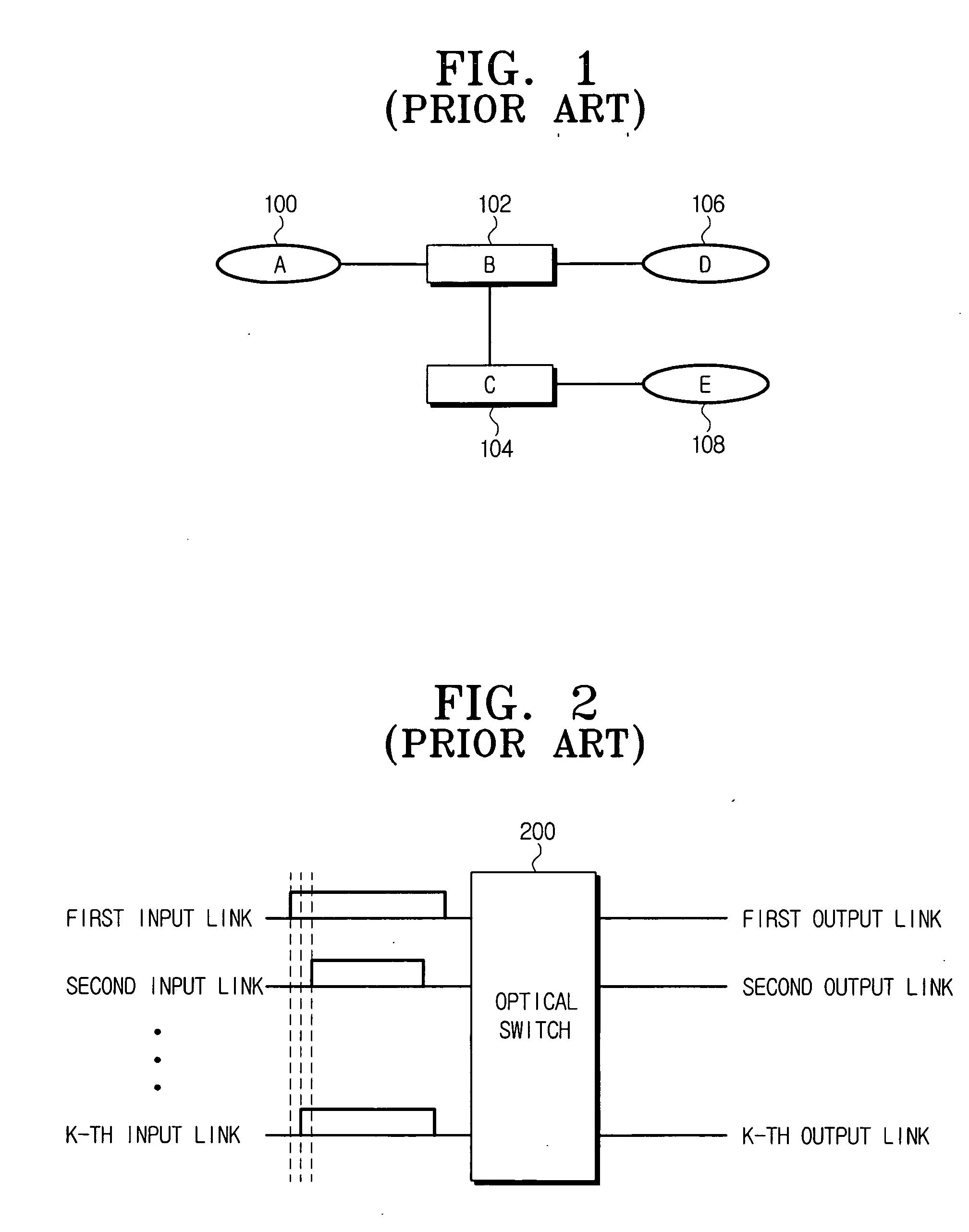
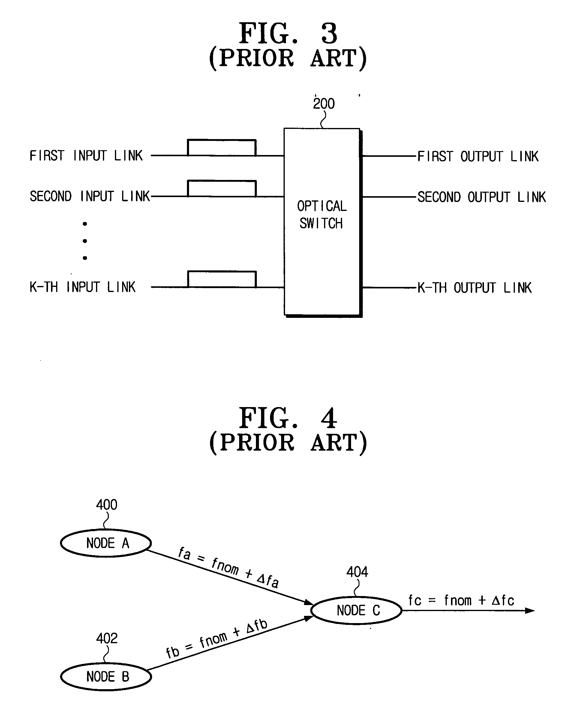
If the burst data input to the optical switch have different sizes and input time points, the switching efficiency of the optical switch deteriorates.

Method used


Image

  • Apparatus for adjusting receiving time point of burst data in optical burst switching network and method thereof
  • Apparatus for adjusting receiving time point of burst data in optical burst switching network and method thereof
  • Apparatus for adjusting receiving time point of burst data in optical burst switching network and method thereof

Examples


Embodiment Construction

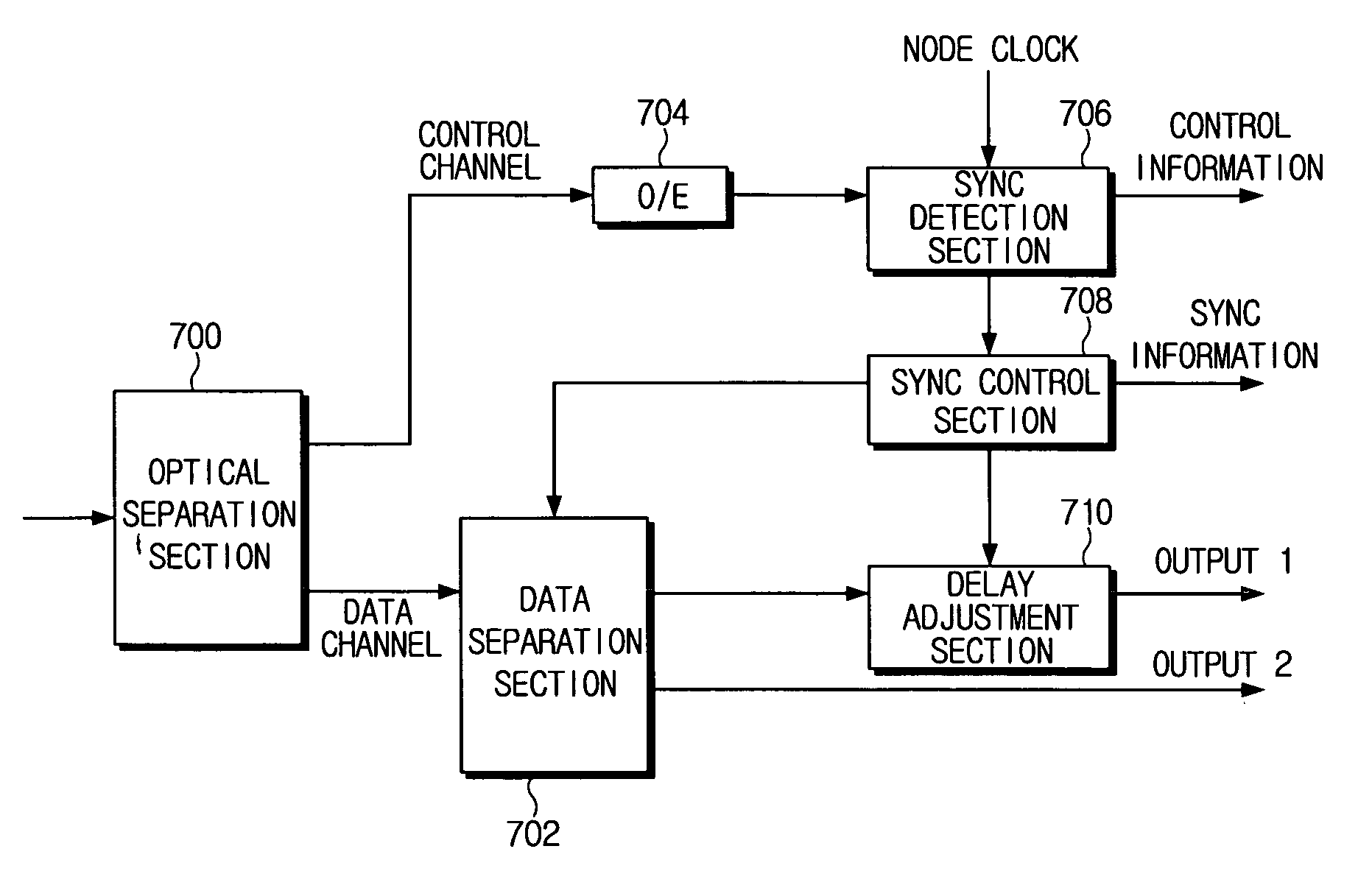
[0036] A method for compensating for the differences among receiving time points of burst data transferred to an optical switch that occurs due to the differences among natural frequencies of links according to exemplary embodiments of the present invention will be described in greater detail with reference to the accompanying drawings.

[0037] In the following description, same drawing reference numerals are used for the same elements even in different drawings. The matters defined in the description such as a detailed construction and elements are provided to assist one skilled in the art with a comprehensive understanding of the invention. Thus, it is apparent that the present invention can be carried out without those defined matters. Also, well-known functions or constructions are not described in detail since they would obscure the invention in unnecessary detail.

[0038]FIG. 6A depicts a code node according to an exemplary embodiment of the present invention.

[0039] As shown in...


PUM


Abstract

An apparatus and method for adjusting a receiving time point of burst data in an optical burst switching network is provided. The method includes comparing a reference time point of a node with a time slot boundary of the burst data; and adjusting the time slot boundary of the burst data in accordance with the reference time point. The apparatus includes a sync detection section which is configured to detect a difference between a time slot boundary of the burst data and a reference time point; and a sync control section which is configured to control shifting and re-aligning the received burst data with the reference time point according to the difference detected by the sync detection section.

Description

CROSS-REFERENCE TO RELATED APPLICATION [0001] This application claims benefit under 35 U.S.C. § 119 (a) from Korean Patent Application No. 2004-117774 filed on Dec. 31, 2004 in the Korean Intellectual Property Office and Korean Patent Application No. 2005-119366 filed on Dec. 8, 2005 in the Korean Intellectual Property Office, and the entire contents of these two Applications are incorporated herein by reference. BACKGROUND OF THE INVENTION [0002] 1. Field of the Invention [0003] The present invention relates generally to an optical burst switching (OBS) network. More particularly, the present invention relates to an apparatus and method for adjusting a receiving time point of burst data and performing synchronization by compensating for a difference of the receiving time point of the burst data and a reference clock of a node which results from physical differences of links connecting nodes in an OBS network. [0004] 2. Description of the Related Art [0005] Generally, an electric sw...

Claims


Application Information

Patent Timeline
Patent Type & Authority Applications(United States)
IPC IPC(8): H04J3/06
CPCH04J3/0685H04J14/0226H04L7/0008H04L7/0075H04Q11/0005H04Q11/0066H04Q2011/0016H04Q2011/0024H04Q2011/0039H04Q2011/0045H04J14/0246H04L7/0041
Inventor DEN HOLLANDER, CORNELIS JOHANNISGARNER, GEOFFREY M.
Owner SAMSUNG ELECTRONICS CO LTD
Why Eureka
Try Eureka