
Perceptual coding of image signals using separated irrelevancy reduction and redundancy reduction

Inactive Publication Date: 2006-07-06
AGERE SYST INC
View PDF14 Cites 31 Cited by
  • Summary
  • Abstract
  • Description
  • Claims
  • Application Information

AI Technical Summary

Benefits of technology

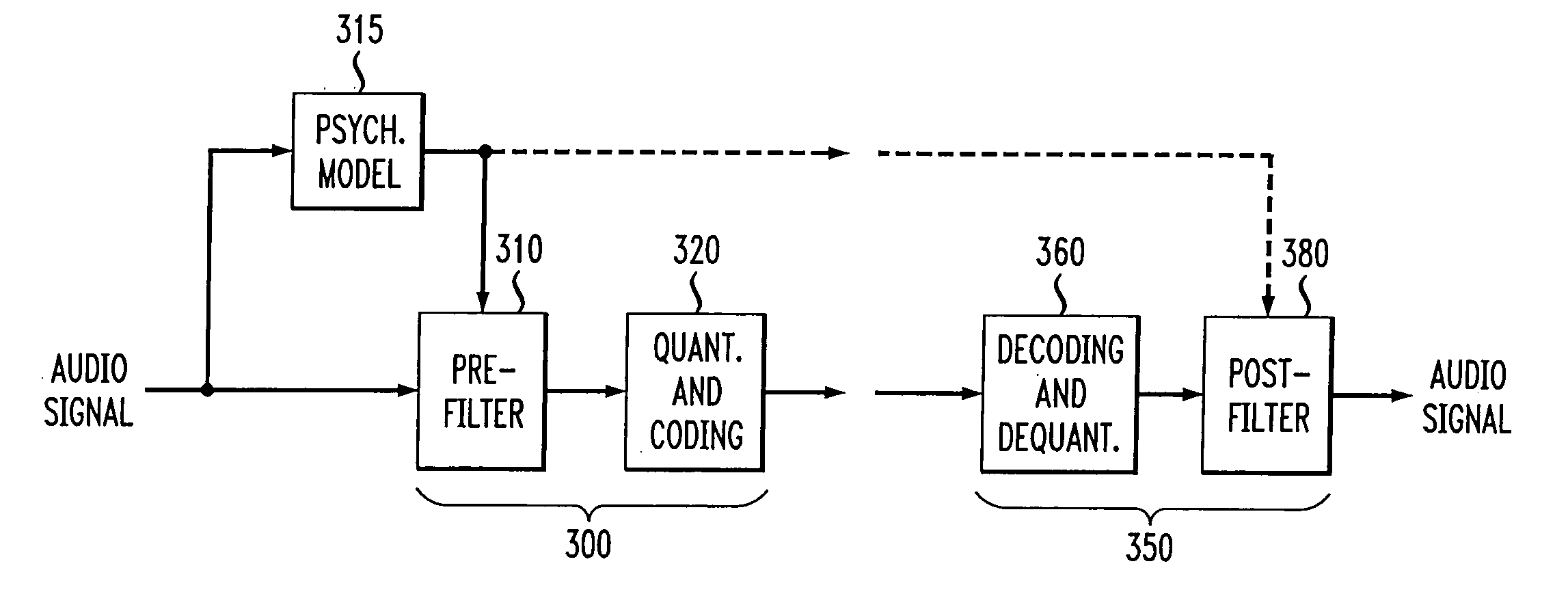
[0013] According to one aspect of the invention, the disclosed perceptual image coder uses fixed quantizer step-sizes, since spectral shaping is performed by the pre-filter prior to quantization and coding. Thus, additional quantizer control information does not need to be transmitted to the decoder, thereby conserving transmitted bits.
[0015] The characteristics of the pre-filter may be adapted to the masked thresholds, using techniques known from speech coding, where linear-predictive coefficient (LPC) filter parameters are used to model the spectral envelope of the speech signal. Likewise, the filter coefficients may be efficiently transmitted to the decoder for use by the post-filter using well-established techniques from speech coding, such as an LSP (line spectral pairs) representation, temporal interpolation, or vector quantization.

Problems solved by technology

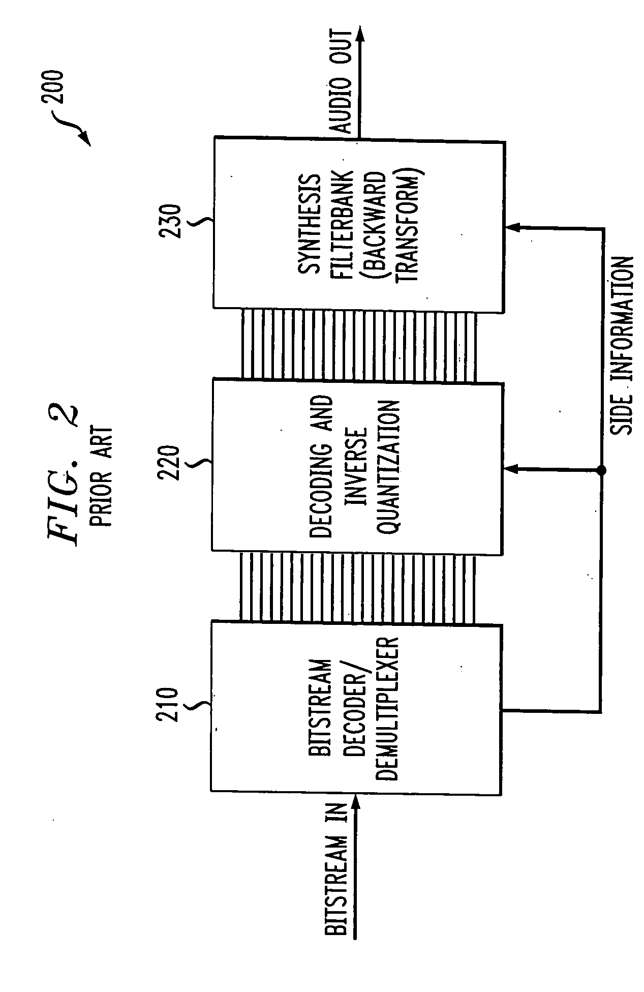
This results in a temporally and spectrally shaped quantization error after the inverse transform at the receiver 200.
One problem encountered in audio transform coding schemes is the selection of the optimum transform length.
While high spectral resolution yields a high degree of redundancy reduction, the resulting long transform window size causes reverbation artifacts, impairing the irrelevancy reduction.

Method used


Image

  • Perceptual coding of image signals using separated irrelevancy reduction and redundancy reduction
  • Perceptual coding of image signals using separated irrelevancy reduction and redundancy reduction
  • Perceptual coding of image signals using separated irrelevancy reduction and redundancy reduction

Examples


Embodiment Construction

[0023] The present invention provides methods and apparatus for perceptual coding of image signals. While the present invention is primarily illustrated herein in the context of audio signals, the techniques of the present invention are applicable to the encoding of image signals as well, as would be apparent to a person of ordinary skill in the art.

[0024]FIG. 3 is a schematic block diagram of a perceptual audio coder 300 according to the present invention and its corresponding perceptual audio decoder 350, for communicating an audio signal, such as speech or music. While the present invention is illustrated using audio signals, it is noted that the present invention can be applied to the coding of other signals, such as the temporal, spectral, and spatial sensitivity of the human visual system, as would be apparent to a person of ordinary skill in the art, based on the disclosure herein.

[0025] According to one feature of the present invention, the perceptual audio coder 300 separ...


PUM


Abstract

A perceptual coder is disclosed for encoding image signals, such as speech or music, with different spectral and temporal resolutions for redundancy reduction and irrelevancy reduction. The image signal is initially spectrally shaped using a prefilter. The prefilter output samples are thereafter quantized and coded to minimize the mean square error (MSE) across the spectrum. The disclosed perceptual image coder can use fixed quantizer step-sizes, since spectral shaping is performed by the pre-filter prior to quantization and coding. The disclosed pre-filter and post-filter support the appropriate frequency dependent temporal and spectral resolution for irrelevancy reduction. A filter structure based on a frequency-warping technique is used that allows filter design based on a non-linear frequency scale. The characteristics of the pre-filter may be adapted to the masked thresholds, using techniques known from speech coding, where linear-predictive coefficient (LPC) filter parameters are used to model the spectral envelope of the speech signal. Likewise, the filter coefficients may be efficiently transmitted to the decoder for use by the post-filter using well-established techniques from speech coding, such as an LSP (line spectral pairs) representation, temporal interpolation, or vector quantization.

Description

CROSS-REFERENCE TO RELATED APPLICATIONS [0001] The present invention is a divisional of U.S. patent application Ser. No. 09 / 586,072, filed Jun. 2, 2000, which is related to U.S. Pat. No. 6,778,953 B1 entitled “Method and Apparatus for Representing Masked Thresholds in a Perceptual Audio Coder,” U.S. Pat. No. 6,678,647 B1 entitled “Perceptual Coding of Audio Signals Using Cascaded Filterbanks for Performing Irrelevancy Reduction and Redundancy Reduction With Different Spectral / Temporal Resolution,” U.S. Pat. No. 6,718,300 entitled “Method and Apparatus for Reducing Aliasing in Cascaded Filter Banks,” and U.S. Pat. No. 6,647,365 entitled “Method and Apparatus for Detecting Noise-Like Signal Components,” assigned to the assignee of the present invention and incorporated by reference herein.FIELD OF THE INVENTION [0002] The present invention relates generally to image coding techniques, and more particularly, to perceptually-based coding of image signals. BACKGROUND OF THE INVENTION [00...

Claims


Application Information

Patent Timeline
IPC IPC(8): G06K9/40G10L19/00H03M7/30
CPCG10L19/02
Inventor EDLER, BERND ANDREASSCHULLER, GERALD DIETRICH
Owner AGERE SYST INC
Learn More