Developer container and image forming apparatus

a technology of container and developer, applied in the direction of electrographic process apparatus, instruments, optics, etc., can solve the problems of coagulation of developer in the neighborhood and easy damage to the container main body, and achieve the effect of softening the coagulation of developer quickly

Inactive Publication Date: 2006-07-06
SHARP KK
View PDF2 Cites 13 Cited by
  • Summary
  • Abstract
  • Description
  • Claims
  • Application Information

AI Technical Summary

Benefits of technology

[0011] Accordingly, an object of the invention is to provide a developer container which is capable of preventing as much as possible a twisting force from the outside about an axial direction of a container main body, a bending force from the outside, a pushing force inward in a radial direction, and damage and deformation by an impact, and moreover preventing as much as possible a developer from being coagulated and further softening the coagulated developer rapidly, and an image forming apparatus on which the developer container is detachably mounted.

Problems solved by technology

Accordingly, there is a danger that the developer is coagulated in the neighborhood of the projection pieces and the developer is supplied to an image forming apparatus in such a coagulated state.
Further, in this case, when the container main body is given a twisting force from the outside about the axis, a bending force from the outside and an impact, there is a danger that the container main body is easily damaged by the occurrence of cracks which extend substantially along the spiral direction in the conveying means of the container main body.

Method used


Image

  • Developer container and image forming apparatus
  • Developer container and image forming apparatus
  • Developer container and image forming apparatus

Examples


first embodiment

[0135] As described above, according to the developer container 30A in the embodiment, the same effect as the above-described developer container 30 of the first embodiment can be achieved.

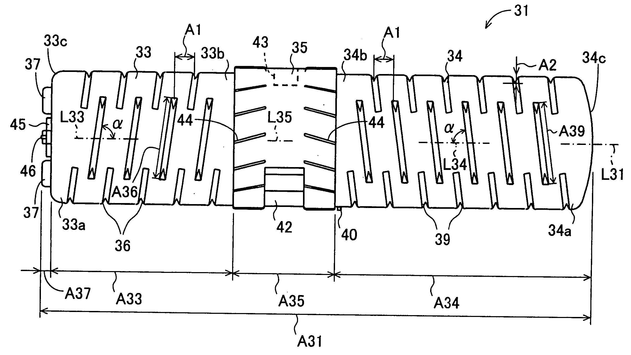
[0136] Moreover, according to the developer container 30A of the embodiment, the first projection portion 36a formed in a close portion to the discharge hole 43 is formed so as to have a larger size in the first extending direction in comparison with the first projection portion 36b formed in a distant portion from the discharge hole 43. Accordingly, the conveying amount in the axial direction of the developer close to the discharge hole 43 at the time when the container main body 31 is rotated is made larger than the conveying amount in the axial direction of the developer far away from the discharge hole 43 and therefore, the conveying amount of the developer can be made uneven with respect to the axial direction. In the case where the conveying amount of the developer is uniform with respect to...

fourth embodiment

[0145]FIG. 26 is a sectional view showing an image forming apparatus 70 of the invention. FIG. 27 is an enlarged sectional view showing a neighborhood of the toner hopper 72. FIG. 28 is an enlarged plan view showing the neighborhood of the toner hopper 72. FIG. 26 is a sectional view of the image forming apparatus 70, taken from the front-side exterior portion 71a side. In order to make the comprehension easy, the thickness is omitted in the view. The front-side exterior portion 71a is generally defined as a portion that is faced by a user when the user uses the image forming apparatus 70. A back-side exterior portion 71b is defined as a portion in the image forming apparatus 70 that is located on the rear side to the front-side exterior portion 71a when seen by the user on the front-side exterior portion 71a side. Further, the image forming apparatus 70 is installed on a horizontal plane. The front to rear direction E, which is directed from the front-side exterior portion 71a to t...


PUM


Abstract

An object of the invention is to provide a developer container in which a container main body is protected against damage by an external torsional and bending force and an impact as much as possible, developer in the vicinity of conveying means is prevented from aggregating as much as possible, and developer in the vicinity of a discharge hole is prevented from aggregating as much as possible. The developer container includes a cylindrical container main body (31) for containing developer for use in image formation, and is detachably mounted on an image forming apparatus, the container main body (31) being rotated about an axis thereof by drive means provided in the image forming apparatus to supply developer to the image forming apparatus, wherein conveying means for conveying the developer in an axial direction when the container main body is rotated about the axis is provided in an inner circumferential portion of the container main body (31), and the conveying means has a plurality of first and second protrusions (36, 39) extending in first and second extending directions and arranged at intervals in a circumferential direction and the axial direction.

Description

TECHNICAL FIELD [0001] The present invention relates to a developer container for containing a toner for use in formation of electrographic images, and an image forming apparatus having the developer container detachably mounted thereon. BACKGROUND ART [0002]FIG. 30(1) is a sectional view showing a toner bottle 1 according to a first conventional art. FIG. 30(2) is a perspective view showing the toner bottle 1. The toner bottle 1 is formed into a substantially cylindrical form having a bottom, and is provided with a housing space 2 for containing toner. The toner bottle 1 is provided with a projection piece 5 protruding inward in the radial direction and extending spirally with an axis L1 as a center from one end portion 3 in the axial direction to the other end portion 4 in the axial direction. The other end portion 4 in the axial direction of the toner bottle 1 is provided an opening portion 6 in which a hole having a smaller inner diameter than that of the remaining portions is f...

Claims


Application Information

Patent Timeline
Patent Type & Authority Applications(United States)
IPC IPC(8): G03G15/08B65D83/06
CPCG03G2215/067G03G15/0886G03G15/0872
Inventor NAGAHAMA, HITOSHIDEGUCHI, MASANOBUKOYAMA, KAZUYAHAYASHI, SHIGEKI
Owner SHARP KK
Why Eureka
Try Eureka