Portable drilling machine

a drilling machine and portability technology, applied in the field of portability drilling machines, can solve the problems of limited dust collection space, corrugated tubes 122/b> may interfere with the rotational motion of the drill bit, etc., and achieve the effect of convenient inspection and easy handling

Inactive Publication Date: 2006-07-06
LEE SEOK JAE
View PDF17 Cites 41 Cited by
  • Summary
  • Abstract
  • Description
  • Claims
  • Application Information

AI Technical Summary

Benefits of technology

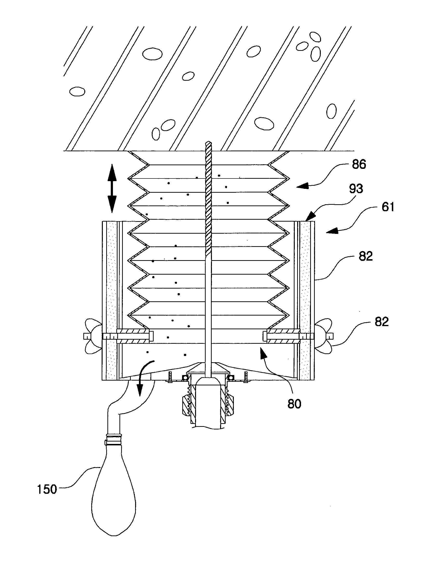
[0018] Accordingly, the present invention has been made to solve the above-mentioned problems occurring in the prior art, and an object of the present invention is to provide a portable drilling machine capable of preventing a dust collector from interfering with the rotational motion of a drill bit and increasing dust collection space.
[0022] A filling member may be mounted in the retaining slot, in order to prevent dust, which is collected by the rear anti-dust cover, from scattering via the retaining slot and stably maintain the coupling condition of front anti-dust cover.
[0023] Preferably, the filling member has a pair of screening members formed on both sides of the fastener, respectively, and a connector for connecting the screening members to each other along the longitudinal direction, so that the filling member can be easily mounted in the retaining slot.
[0027] Preferably, at least one of the rear and front anti-dust covers is made of a transparent material, so that the drilling operation can be easily checked by the naked eye.
[0028] The rear anti-dust cover may have a dust discharge hole formed adjacent to the drill through-hole, and the dust collector may have a collector connected to an inner space of the rear anti-dust cover via a conduit connected to the dust discharge hole, so that dust collected by the anti-dust cover can be easily dealt with.

Problems solved by technology

However, the conventional portable drilling machine has a problem in that, when the corrugated tube 122 extends / retracts with a slant relative to the longitudinal direction of the drill bit 113 during drilling operation, the corrugated tube 122 may interfere with the rotational motion of the drill bit 113 (i.e. drilling operation) by making contact with it.
This means that dust collection space is limited.

Method used


Image

  • Portable drilling machine
  • Portable drilling machine
  • Portable drilling machine

Examples


Embodiment Construction

[0041] Hereinafter, a preferred embodiment of the present invention will be described with reference to the accompanying drawings. In the following description and drawings, the same reference numerals are used to designate the same or similar components, and so repetition of the description on the same or similar components will be omitted.

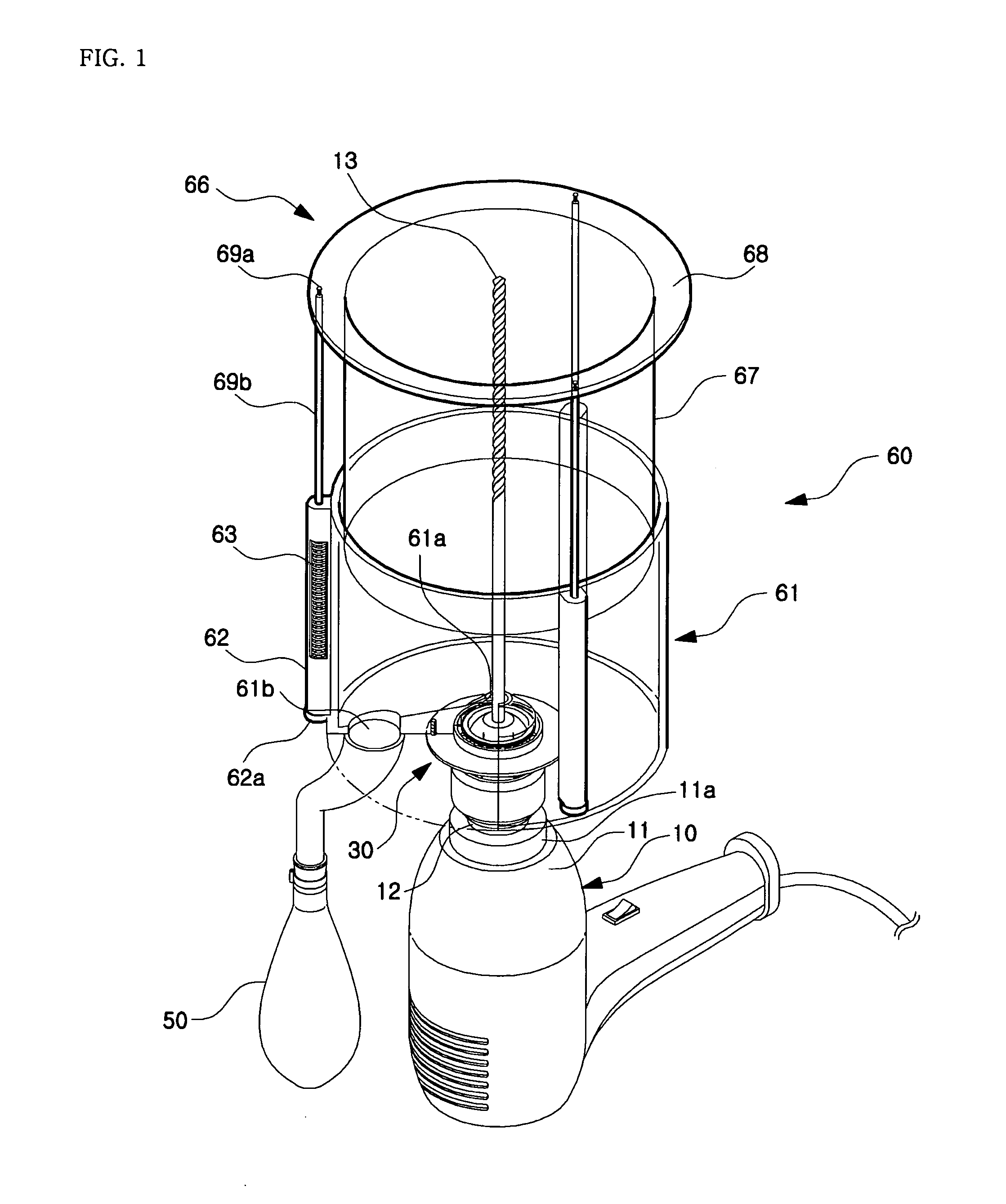
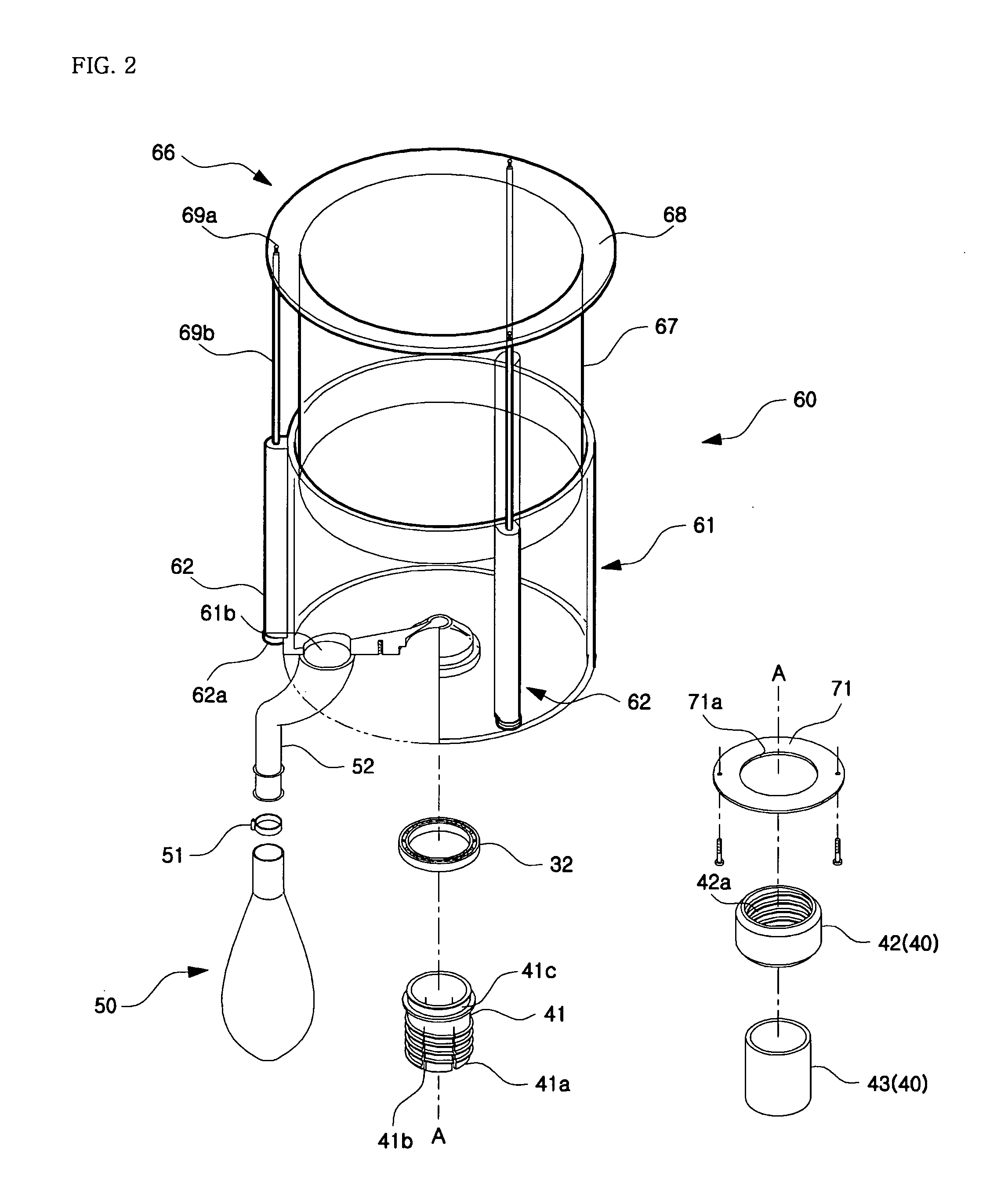
[0042]FIG. 1 is a coupled perspective view showing a portable drilling machine according to an embodiment of the present invention. FIGS. 2, 3, and 4 are exploded perspective views showing a portable drilling machine according to an embodiment of the present invention. FIGS. 5, 6, 7, and 8 are exploded sectional views showing a portable drilling machine according to an embodiment of the present invention.

[0043] A portable drilling machine according to an embodiment of the present invention, as shown in the drawings, includes a drill 10 and a dust collector 20 coupled to the front end of the drill 10.

[0044] The drill 10 includes a housing 11 ha...


PUM

PropertyMeasurementUnit
rotational driving forceaaaaaaaaaa
pressureaaaaaaaaaa
elasticaaaaaaaaaa

Abstract

A portable drilling machine includes a housing; a drill chuck positioned on a front surface of the housing; a drill bit detachably coupled to the drill chuck; a driver positioned inside the housing to provide either the drill bit or the drill chuck with a rotational driving force; an anti-dust cover having a rear anti-dust cover formed in a cup shape with a drill through-hole formed in a central region of a bottom surface of the rear anti-dust cover and a front anti-dust cover formed in a tube shape to be coupled to the rear anti-dust cover, the front anti-dust cover being adapted to move towards the bottom surface of the rear anti-dust cover when acted on by pressure towards the housing and return to original position when the pressure is removed; and a dust collector having a retainer for detachably coupling the rear anti-dust cover to an outer surface of either the housing or the drill chuck. The rotational motion of the drill bit is not interfered with by the dust collector, and the dust collection space is increased.

Description

BACKGROUND OF THE INVENTION [0001] 1. Field of the Invention [0002] The present invention relates to a portable drilling machine, and more particularly to a portable drilling machine adapted to be carried by an operator to perform drilling operation. [0003] 2. Description of the Prior Art [0004] As generally known in the art, portable drilling machines are used to drill holes in walls when, for example, anchors need to be installed at a construction site related to electricity, facility, or hardware. Korean Patent Application No. 2000-11714 (entitled “Multi-functional dust collection device for drill”) discloses a portable drilling machine having a means for collecting dust, which is created during drilling operation. [0005]FIG. 18 is an exploded perspective view of a conventional portable drilling machine, and FIG. 19 is an assembled perspective view thereof. [0006] A conventional portable drilling machine, as shown in the drawings, includes a drill 110, a dust collector 120 couple...

Claims


Application Information

Patent Timeline
Patent Type & Authority Applications(United States)
IPC IPC(8): B23B47/00B23Q11/00
CPCB23B49/008B23Q11/0042B23Q11/0071Y10T409/304088Y10T408/50Y10T408/44Y10T408/51
Inventor KIM, JONG OH
Owner LEE SEOK JAE
Why Eureka
Try Eureka