
Power injection catheters

a technology of injection catheter and power, which is applied in the direction of catheter, intravenous device, other medical devices, etc., can solve the problems of burst disk damage, breakage, etc., and achieve the effect of preventing overpressurizing the first lumen

Active Publication Date: 2006-07-06
CR BARD INC
View PDF41 Cites 74 Cited by
  • Summary
  • Abstract
  • Description
  • Claims
  • Application Information

AI Technical Summary

Benefits of technology

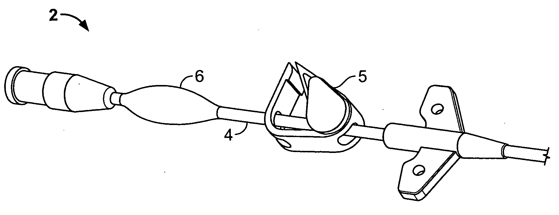
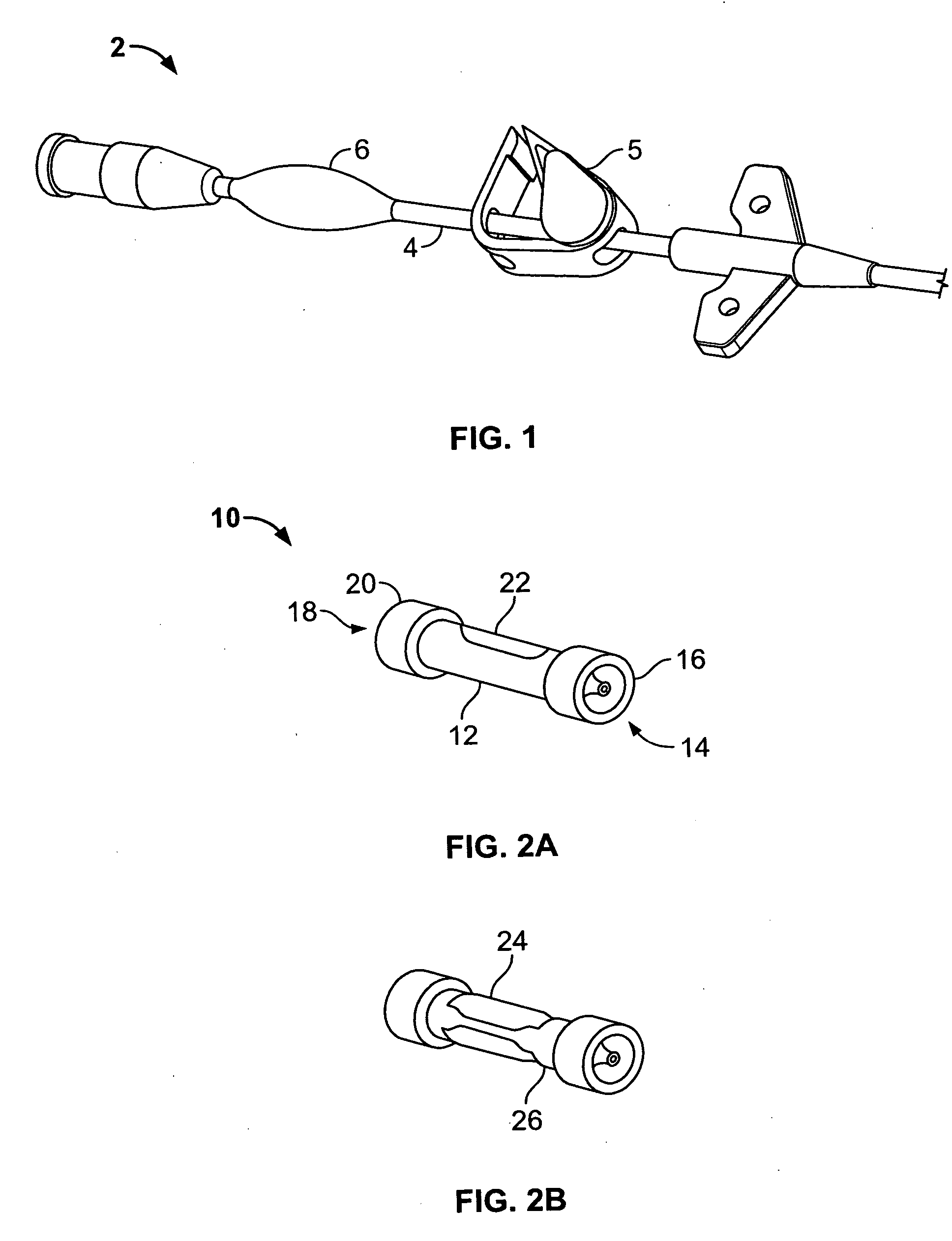
[0009] Described herein are catheters for infusing fluids into a patient's body. Some variations of the catheter are configured for high flow rate applications. These catheters, which are configured for infusing large amounts of fluids in a short period of time, are termed “power injection catheters.” The catheters may be configured to support high pressure inside its lumen to sustain high pressure generated by rapid infusion. In addition, a pressure relief mechanism may be provided on the catheter to prevent overpressurization. In one variation, the power injection catheter comprises a pressure buffering component / unit connected to or integrated into the proximal portion of a catheter. The pressure buffering component prevents sudden pressure build-up inside the lumen of the catheter by (1) absorbing / buffering, or (2) releasing pressure inside the lumen during pressure spikes. The buffering component may comprise a balloon, a diaphragm, or a pressure relief valve, etc. In one configuration, the balloon or diaphragm comprises a non-compliant polymeric material. In another configuration, the balloon or diaphragm comprises a compliant polymeric material.
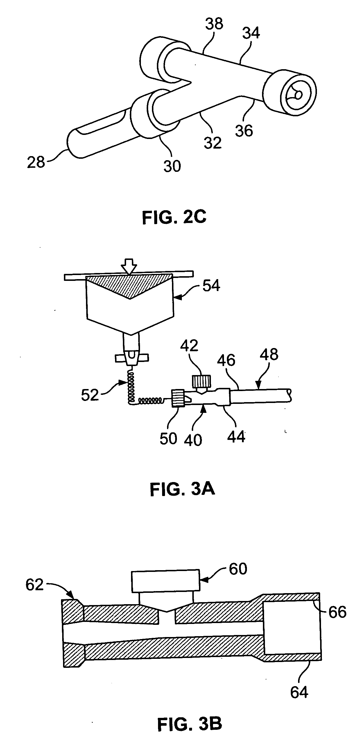
[0010] In another variation, a T-shaped connector is provided for connection to the proximal end of a catheter. The distal end of the T-shape connector is connected to the proximal end of the catheter, and the proximal end of the T-shaped connector can be connected to a fluid source. The perpendicular opening at the mid-section of the T-shaped connector may be covered with a diaphragm, a balloon, a burst disk, or a pressure relief valve. The T-shaped connector may also be designed with a replaceable pressure relief mechanism, such that if overpressurizing causes the pressure relief mechanism to fail, it can be easily replaced. In one configuration, the T-shaped connecter is implemented with a pressure relief mechanism and a balloon positioned over the pressure relief mechanism. The pressure relief mechanism opens when the pressure within the connector exceeded a predefined threshold. The balloon serves as a mechanism to capture the effluent.
[0014] In another variation, a multi-lumen catheter with branching extensions is configured with a valve such that the user can electively establish fluid communication between the various lumens within the catheter. In one particular design, a bifurcating dual lumen catheter is configured with a valve at the bifurcation such that the user may open the valve to establish fluid communication between the two lumens in the catheter. The user can also close the valve in the bifurcation in order to utilize the two lumens independently. In another variation, a unidirectional or a bi-directional pressure driven valve may be utilized between the two lumens. The valve may be configured to open when a predefined pressure value is exceeded. When the pressure in the first lumen exceeds the predefined pressure value, the valve opens and allows fluid to flow into the adjacent lumen to prevent overpressurizing of the first lumen.

Problems solved by technology

When the lumen pressure exceeds the predefined pressure threshold supported by the burst disk, the burst disk is compromised and breaks.

Method used


Image

  • Power injection catheters
  • Power injection catheters
  • Power injection catheters

Examples


Embodiment Construction

[0037] The following detailed description should be read with reference to the drawings, in which like elements in different drawings may be identically numbered. The drawings, which are not necessarily to scale, depict selected preferred embodiments and are not intended to limit the scope of the invention. The detailed description illustrates by way of example, not by way of limitation, the principles of the invention. This description will clearly enable one skilled in the art to make and use the invention, and describes several embodiments, adaptations, variations, alternatives and uses of the invention, including what is presently believed to be the best mode of carrying out the invention.

[0038] Before describing the present invention, it is to be understood that unless otherwise indicated this invention need not be limited to applications in humans. As one of ordinary skill in the art would appreciate, variations of the invention may be applied to other mammals as well. Moreov...


PUM


Abstract

A power injection catheter for high flow rate delivery of fluids. The power injection catheter may include a pressure relief mechanism for preventing overpressurizing within the lumen of the catheter. The pressure relief mechanism may be configured to prevent sudden pressure build-up inside the catheter lumen by absorbing, buffering or releasing pressure inside the lumen during pressure spikes. The power injection catheter may also take the form of a multi-lumen catheter capable of simultaneous infusions of a single fluid through two or more of the lumens in the catheter.

Description

CROSS-REFERENCE TO RELATED APPLICATIONS [0001] Not applicable. STATEMENT REGARDING FEDERALLY SPONSORED RESEARCH OR DEVELOPMENT [0002] Not applicable. REFERENCE TO A COMPACT DISK APPENDIX [0003] Not applicable. BACKGROUND OF THE INVENTION [0004] It has been observed that during injection of a contrast media at high flow rates into a small-sized lumen, the sudden increase in pressure inside the lumen may lead to failure of the catheter wall. In addition, catheters that are implanted in a patient's body for a period of time may have thrombus build-up within the lumen of the catheter. These thromboses may occlude the catheter and cause overpressurization when the catheter is flushed. To prevent the sudden pressure spikes, a pressure buffering component may be provided to modulate the pressure inside the catheter lumen. Various other medical applications that require high throughput fluid injection through a catheter may also benefit from having a pressure modulating device integrated wi...

Claims


Application Information

Patent Timeline
IPC IPC(8): A61M1/00
CPCA61M5/007A61M5/1408A61M5/16854A61M2205/3355A61M2205/3341
Inventor DIAMOND, JORDAN P.RAJI-KUBBA, ABTIHALBARRON, WILLIAM R.BREITER, CATHERINE C.
Owner CR BARD INC
Learn More