Accommodating arching lens

a technology of arching lens and accommodating frame, which is applied in the field of new accommodating intraocular lenses, can solve the problems of degrading or completely destroying the ability of the eye to function properly, bifocal intraocular lenses, and only about 40% of available light in bifocal images, so as to achieve the effect of improving accommodation

Inactive Publication Date: 2006-07-06
C& C VISION INT
View PDF70 Cites 36 Cited by
  • Summary
  • Abstract
  • Description
  • Claims
  • Application Information

AI Technical Summary

Benefits of technology

[0009] The present invention relates to accommodating intraocular lenses having a central optic and T-shaped haptics, and having improved accommodation.
[0012] As is known, after surgical implantation of the accommodating intraocular lens in the capsular bag of the eye, active endodermal cells on the posterior side of the anterior capsule rim of the bag cause fibrosis with shrinkage of the bag and fusion of the rim to the elastic posterior capsule of the bag. This fibrosis occurs about the lens extended portions in such a way that these extended portions and the lens are effectively “shrink-wrapped” by the fibrous tissue in such a way as to form radial pockets in the fibrous tissue which contain the extended portions with their outer ends positioned within the outer cul-de-sac of the capsular bag. The lens is thereby fixated within the capsular bag with the lens optic aligned with the anterior capsule opening in the bag. The anterior capsule rim shrinks during fibrosis, and this shrinkage combined with shrink-wrapping of the extended portions causes some radial compression of the lens in a manner which tends to move the lens optic relative to the outer ends of the extended portions posteriorly along the axis of the eye. The fibrosed, leather-like anterior capsule rim prevents anterior movement of the optic and urges the optic rearwardly during fibrosis. Accordingly, fibrosis induced movement of the optic occurs posteriorly to a distant vision position in which either or both the optic and the inner ends of the extended portions press rearwardly against the elastic posterior capsule of the capsular bag and stretch this posterior capsule rearwardly.
[0013] Normal brain-induced contraction of the muscle relaxes the zonules and anterior capsule rim, and increases vitreous pressure in the vitreous cavity of the eye. This normal contraction of the ciliary muscle effects anterior accommodation movement of the lens optic for near vision by the combined action of the increased vitreous pressure, anterior capsule rim relaxation, and the anterior bias of the stretched posterior capsule. Similarly, brain-induced relaxation of the ciliary muscle reduces vitreous pressure, relieves radial compression of the lens, and stretches the anterior capsule rim to effect posterior movement of the lens optic for distant vision.
[0015] Thus the optic moves anteriorly and posteriorly relative to the outer ends of the haptics to create a near reading effect. Importantly, it has been discovered that the optic positively bends or bows in order to enhance near and intermediate vision capability. This bending is a result of forward vitreous pressure and / or capsular contraction creating a warpage (that is, bending or bowing) of the thin optic that enhances the patients' ability to read. This warpage is created by ciliary muscle constriction, resulting in relaxation of the zonules which then allows circumferential relaxation of the capsule allowing the optic of the lens to move forward and deform, creating the effect of additional minus power in the lens optic along with forward movement thereby enhancing the ability of the patient to see at intermediate and near. Also, the increase in vitreous cavity pressure can tilt the lens optic to further facilitate accommodation.
[0023] The extended portions of a presently preferred lens embodiment are generally T-shaped haptics each including a haptic plate and a pair of relatively slender resiliently flexible fixation fingers at the outer end of the haptic plate. In their normal unstressed state (e.g., FIG. 2), the two fixation fingers at the outer end of each haptic plate extend laterally outward from opposite edges of the respective haptic plate in the plane of the plate and substantially flush with the radially outer end edge of the plate to form the horizontal “crossbar” of the haptic T-shape. The radially outer end edges of the haptic plates (the fixation fingers) are slightly circularly curved about the central axis of the lens optic to substantially equal radii closely approximating the radius of the interior perimeter of the capsular bag when the ciliary muscle of the eye is relaxed. During implantation of the lens in the bag, the inner perimetrical wall of the bag deflects the haptic fingers generally radially inward from their normal unstressed positions to arcuate bent configurations (FIG. 7) in which the radially outer edges of the fingers and the curved outer end edges of the respective haptic plates conform approximately to a common circular curvature closely approximating the curvature of the inner perimetrical wall of the bag. The outer T-ends of the haptics then press lightly against the perimetrical bag wall and are fixated within the bag perimeter during fibrosis with approximation of the anterior capsule to the posterior capsule to accurately center the implanted lens in the bag with the lens optic aligned with the anterior capsule opening in the bag.
[0024] The haptic plates of certain described lens embodiments are narrower in width than the optic diameter and are tapered so as to narrow in width toward their outer ends. These relatively narrow plates of the haptics flex or pivot relatively easily to aid the accommodating action of the lens and form haptic pockets of maximum length in the fibrous tissue between the haptic fingers and the optic which maximize the accommodation movement of the lens optic. The tapered haptics, being wider adjacent to the optic, can slide radially in the capsular bag pockets during contraction of the ciliary muscle to enable forward movement of the optic for vision accommodation.

Problems solved by technology

The human eye is subject to a variety of disorders which degrade or totally destroy the ability of the eye to function properly.
Bifocal intraocular lenses, however, suffer from the disadvantage that each bifocal image represents only about 40% of the available light, and a remaining 20% of the light is lost in scatter.

Method used


Image

  • Accommodating arching lens
  • Accommodating arching lens
  • Accommodating arching lens

Examples


Embodiment Construction

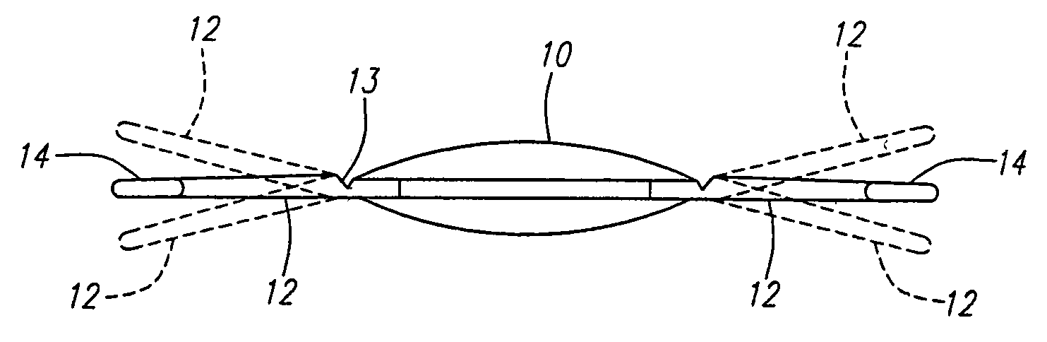
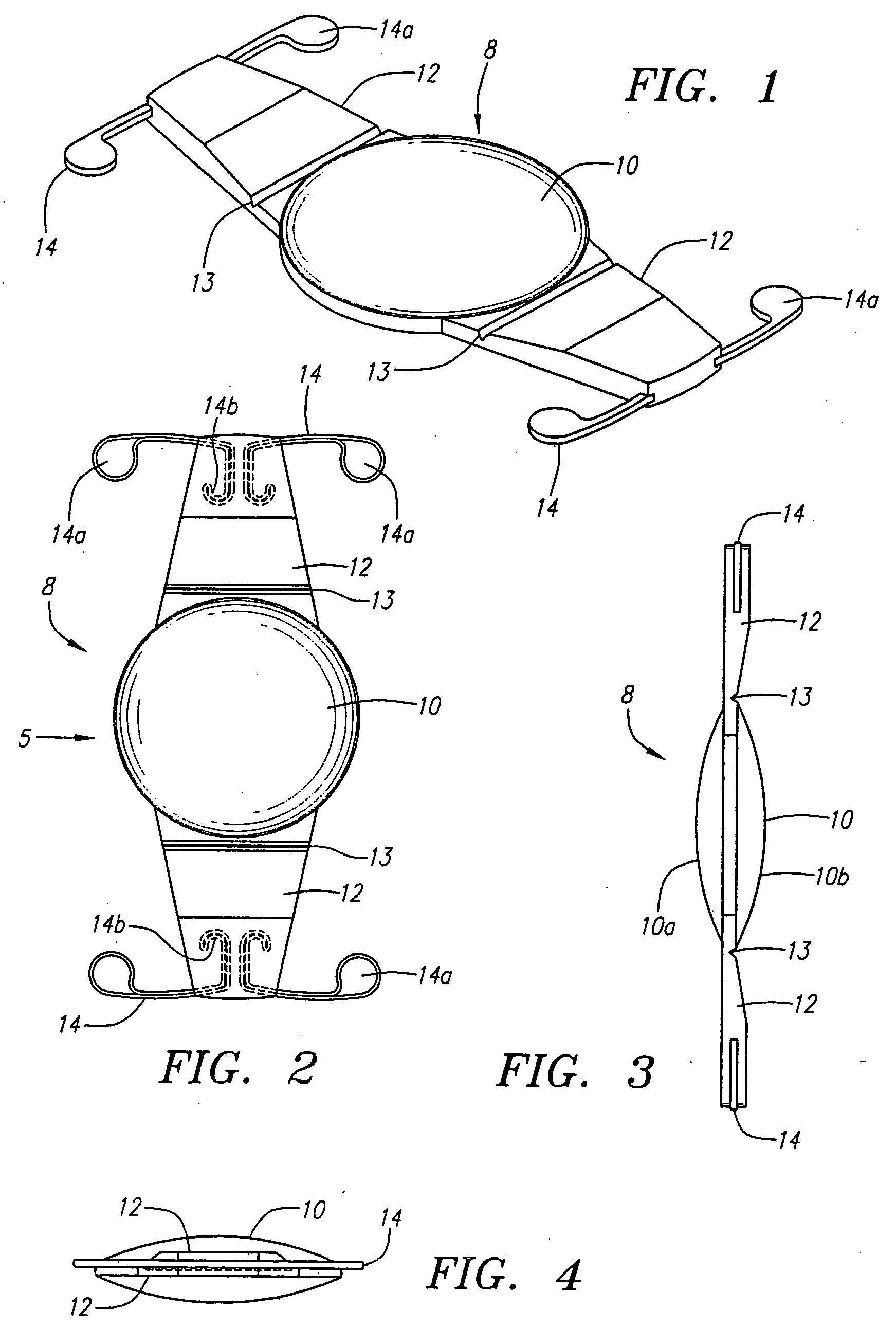
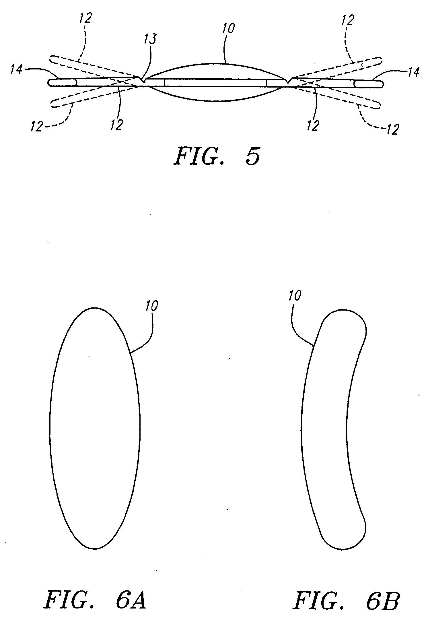
[0038] Turning now to FIGS. 1 through 4, an intraocular lens 8 according to the present invention is shown in detail and which replaces and performs the accommodation function of a removed human crystalen lens. The lens 8 may be utilized to replace either a natural lens which is virtually totally defective, such as a cataractious natural lens, or a natural lens that provides satisfactory vision at one distance without the wearing of glasses but provides satisfactory vision at another distance only when glasses are worn. For example, the accommodating intraocular lens of the invention can be utilized to correct refractive errors and restore accommodation for persons in their mid-40s or older who require reading glasses or bifocals for near vision.

[0039] Intraocular lens 8 comprises a flexible unitary lens body, including a flexible biconvex solid optic 10, which may be formed of relatively hard material, relatively soft flexible semi-rigid material, or a combination of both hard and...


PUM


Abstract

A flexible accommodating intraocular lens having anteriorly and posteriorly movable extended portions, such as T-shaped haptics, extending from a central solid biconvex optic to be implanted within a natural capsular bag of a human eye with the extended portions positioned between an anterior capsular rim and a posterior capsule of the bag, whereby during a post-operative healing period, fibrosis occurs about the extended portions to fixate the lens in the bag in a manner such that subsequent natural contraction and relaxation of the ciliary muscle moves and deforms the optic to provide vision accommodation.

Description

[0001] This application is a continuation-in-part of Ser. No. 11 / 182,195 filed Jul. 14, 2005 which was a continuation in part of Ser. No. 10 / 994,045 filed May 19, 2005, which was a continuation-in-part of Application Ser. No. 60 / 613,009 filed Sep. 24, 2004, which is a continuation-in-part of application Ser. No. 10 / 454,280 filed Jun. 3, 2003, which is a continuation of application Ser. No. 10 / 057,691 filed Jan. 24, 2002, now U.S. Pat. No. 6,638,306, which is a divisional of application Ser. No. 08 / 858,978 filed May 20, 1997, now U.S. Pat. No. 6,387,126.BACKGROUND OF THE INVENTION [0002] This invention relates generally to intraocular lenses to be implanted within a natural capsular bag in the human eye formed by evacuation of the crystalline matrix from the natural lens of the eye through an anterior capsulotomy in the lens. The invention relates more particularly to novel accommodating intraocular lenses of this kind having improved features including an optic and T-shaped haptics....

Claims


Application Information

Patent Timeline
Patent Type & Authority Applications(United States)
IPC IPC(8): A61F2/16
CPCA61F2/1613A61F2/1629A61F2002/1689A61F2/1635A61F2/16
Inventor CUMMING, J. STUARTWALTZ, KEVIN
Owner C& C VISION INT
Why Eureka
Try Eureka