Method for managing the "stop-and-start" mode in a motor vehicle equipped with an internal combustion engine

Active Publication Date: 2006-07-13
FAB ITAL MAGNETI MARELLI SPA
View PDF17 Cites 42 Cited by
  • Summary
  • Abstract
  • Description
  • Claims
  • Application Information

AI Technical Summary

Benefits of technology

[0009] The aim of the present invention is to provide a method for managing the “stop-and-start” mode in a motor vehicle equipped with an internal combust

Problems solved by technology

During the starting phase, a considerable amount of electrical energy is consumed by the electric starter motor, which consequently places a great load on and entails considerable loss of electric charge in the battery of the motor vehicle.
Obviously,

Method used


Image

  • Method for managing the "stop-and-start" mode in a motor vehicle equipped with an internal combustion engine
  • Method for managing the "stop-and-start" mode in a motor vehicle equipped with an internal combustion engine
  • Method for managing the "stop-and-start" mode in a motor vehicle equipped with an internal combustion engine

Examples


Embodiment Construction

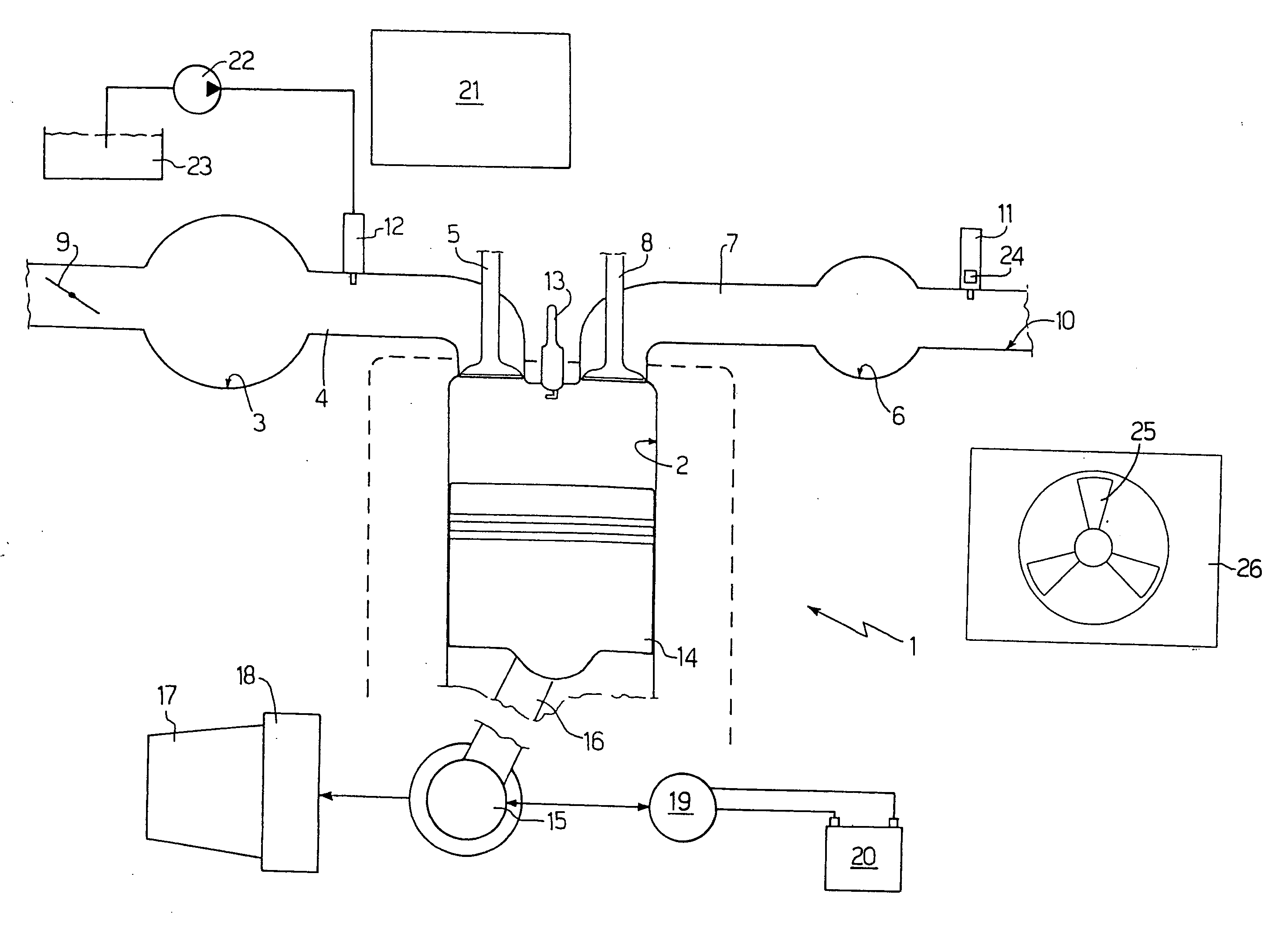
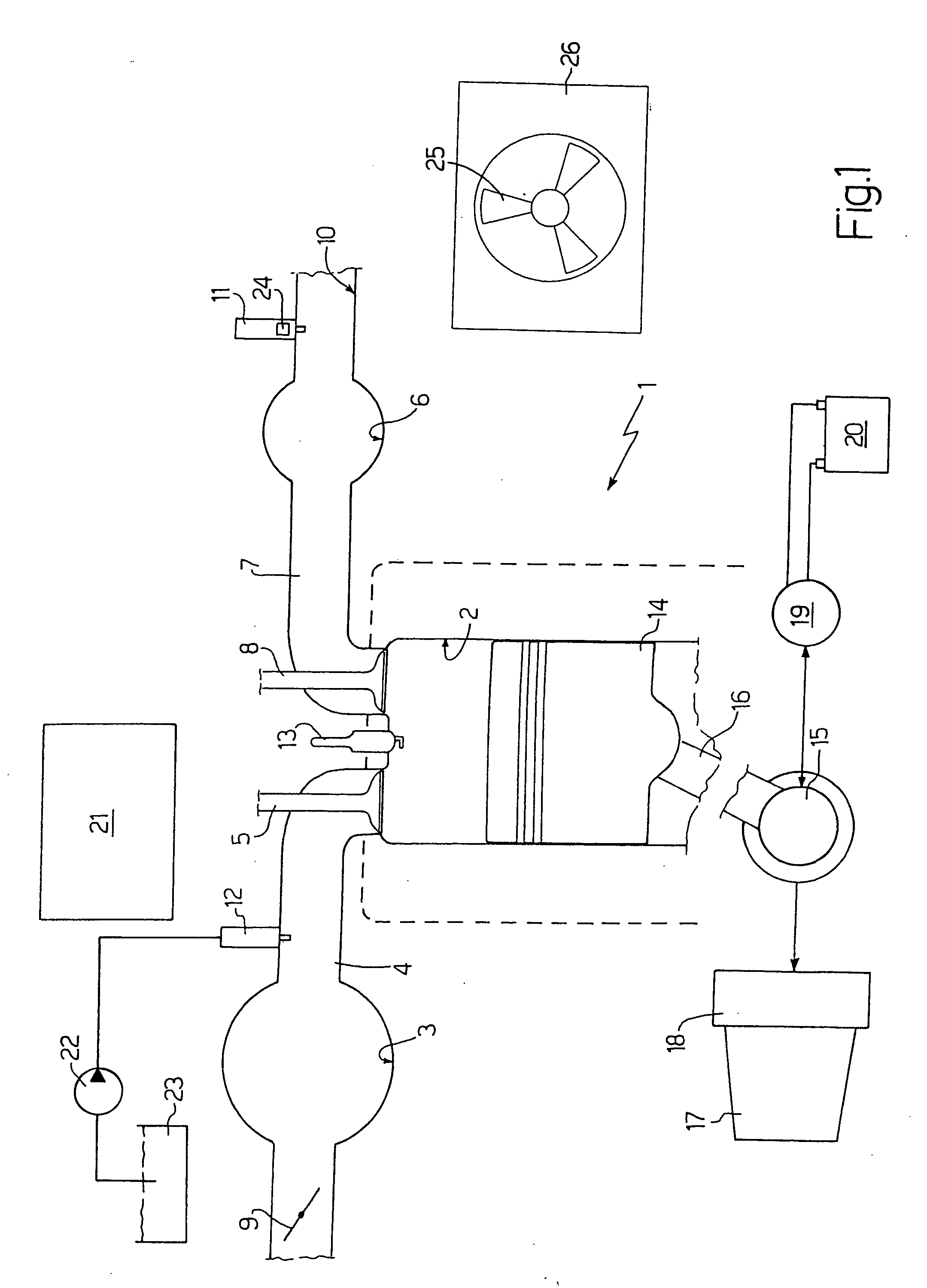
[0014] In FIG. 1, 1 denotes the overall internal combustion engine, which engine 1 comprises four cylinders 2 (only one of which is shown in FIG. 1) arranged in line. Each cylinder 2 is connected to an intake manifold 3 via a dedicated intake duct 4 controlled by at least one intake valve 5 and to an exhaust manifold 6 via a dedicated exhaust duct 7 controlled by at least one exhaust valve 8. The intake manifold 3 receives fresh air (i.e. air originating from the outside environment) via a throttle valve 9 that is adjustable between a closed position and a maximally open position. The exhaust manifold 6 leads to an exhaust system 10 equipped with one or more catalytic converters (not shown in detail) in order to discharge into the atmosphere the gases produced by combustion in the cylinders 2; at least one mixture concentration gauge 11 is arranged in the exhaust system 10 (in particular a lambda probe 11).

[0015] Four injectors 12 (one for each cylinder 2) are coupled to the respec...


PUM


Abstract

A method for managing the “stop-and-start” mode in a motor vehicle equipped with an internal combustion engine; the method provides for the “stop-and-start” mode to be enabled or disabled as a function of a state of charge (SOC) of a battery of the motor vehicle, as a function of a state of motion of a driveshaft of the internal combustion engine and as a function of the electric power consumed overall by the electrical consumers of the motor vehicle.

Description

[0001] The present invention relates to a method for managing the “stop-and-start” mode in a motor vehicle equipped with an internal combustion engine (ICE). BACKGROUND OF THE INVENTION [0002] An internal combustion engine comprises a number of cylinders (usually four, arranged in line) provided with respective pistons connected to a cranked driveshaft by means of connecting rods; the shaft of an electric starter motor, which is powered by a battery of the motor vehicle, is also connected mechanically to the driveshaft of the internal combustion engine. In order to start the internal combustion engine, the electric motor sets the driveshaft in rotation from an initial position in which said driveshaft is stationary; as soon as the driveshaft begins to rotate, fuel is injected (directly or indirectly) into the cylinders in order to attempt to achieve a first explosion in the shortest possible time and so enable the internal combustion engine to become self-sustaining. [0003] The “sto...

Claims


Application Information

Patent Timeline
IPC IPC(8): F02N17/00F02D45/00F02N11/08F02N99/00
CPCF01P7/048F02D41/042F02D41/1494F02D41/22F02D41/222F02D41/3082F02D2250/31F02N11/04F02N11/0818F02N11/0825F02N2200/061F02N2200/0809Y02T10/48Y02T10/40
Inventor LUPO, SAVINO LUIGIPENNESE, MICHELE
Owner FAB ITAL MAGNETI MARELLI SPA
Why Eureka
Try Eureka