Image processing system

a processing system and image technology, applied in the field of image processing system, can solve the problems of not reproducing color at high fidelity level, heavy weight, and camera setting needs to be checked, and achieve the effect of reducing the unhomogeneity of illumination

Inactive Publication Date: 2006-07-13
OLYMPUS CORP
View PDF80 Cites 42 Cited by
  • Summary
  • Abstract
  • Description
  • Claims
  • Application Information

AI Technical Summary

Benefits of technology

[0020] According to a fifth invention, in the first invention, the image capturing unit further comprises an optical member which reduces the illuminating unhomogeneity between the illuminating light source and the subject.

Problems solved by technology

However, the cameras for skin check disclosed in Japanese Unexamined Patent Application Publication No. 8-149352 and Japanese Unexamined Patent Application Publication No. 7-322103 are handy, however, do not reproduce the color at high fidelity level.
Further, in the color reproducing system at high fidelity level using a rotatably filter disclosed in Japanese Unexamined Patent Application Publication No. 2000-152269, the weight is heavy because the system is fixedly arranged and another illumination sensor is necessary for the color reproduction because of the exterior lighting.
This determination is subjective and is influenced by the deterioration and change in room light, thereby causing an error.
Although the recording operation uses a photograph, the camera setting needs to be checked and the matching of image size is difficult.
Further, it is not accurate because the film sensitivity and the developing sensitivity are not constant.
(1) A color reproducing image system is not proposed to accurately capture spectroscopic image data irrespective of ambient light by a portable photographing apparatus with the simple configuration.
The maintenance is manually executed and therefore the color chip gets easily dirty.
Further, the color chip might be deteriorated due to the exposure to the ambient light, depending on the maintenances.
However, such a color reproducing image system is not proposed.

Method used


Image

  • Image processing system
  • Image processing system
  • Image processing system

Examples


first embodiment

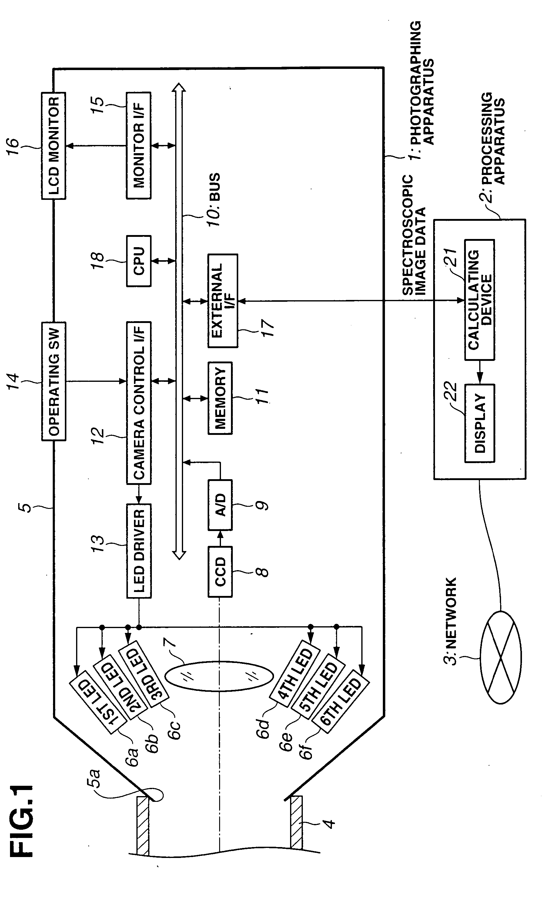
[0102] FIGS. 1 to 16 relate to a first embodiment, FIG. 1 is a block diagram showing the configuration of an image processing system.

[0103] The image processing system comprises: a photographing apparatus 1 which can take a picture of a subject spectroscopic image by illuminating a subject with illuminating light having a plurality of independent varying wavelength bands in a visible light area; and a processing apparatus 2 which is connected to the photographing apparatus 1 and processes the subject spectroscopic image outputted from the photographing apparatus 1. The processing apparatus 2 is connected to a network 3 if necessary.

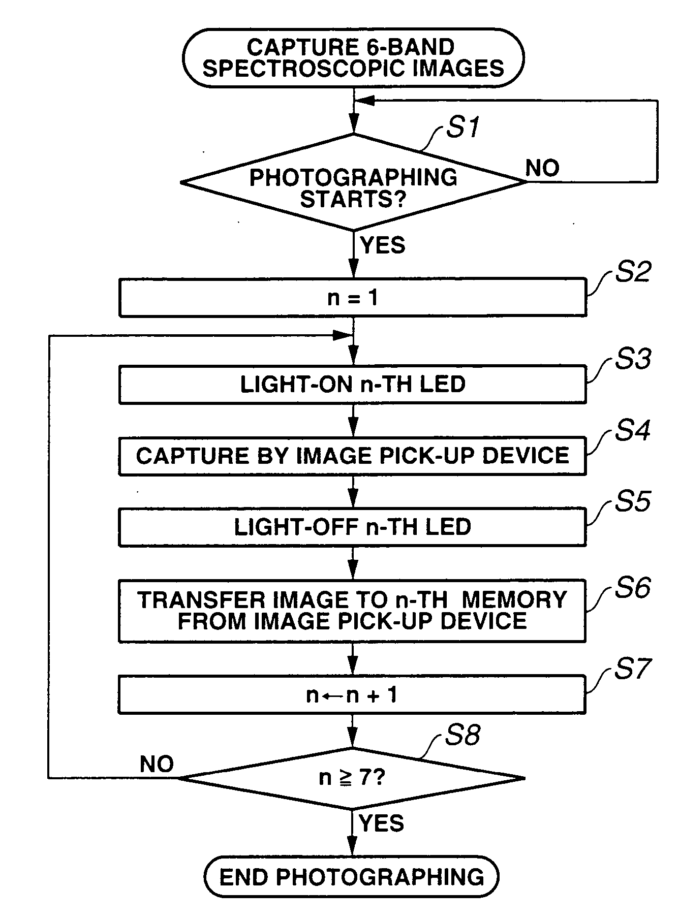
[0104] In the photographing apparatus 1 according to the first embodiment, the image pick-up operation of a still image and the image pick-up operation of a moving image are performed. That is, in the image pick-up operation of the still image, illuminating light having six types of wavelength bands (six primary-color illuminating light) is sequentially ...

second embodiment

[0195] FIGS. 17 to 20 relate to the present invention. FIG. 17 is a block diagram showing the configuration of an image processing system. FIG. 18 is a timing chart showing reading states in a full mode and a double-speed mode. FIG. 19 is a diagram showing a state of lines read in a 2 / 4-line double-speed mode and a 2 / 8-line four-time speed mode. FIG. 20 is a flowchart showing the operation for setting a photographing mode.

[0196] According to the second embodiment, the same components as those according to the first embodiment are designated by the same reference numerals and are not described. Mainly, only different portions are described.

[0197] The second embodiment uses the basic configuration according to the first embodiment. Further, according to the second embodiment, it is possible to adjust an image reading speed from a color CCD having a color filter array (CFA) 19 in front of the image processing system.

[0198] The image reading speed corresponds to a display speed, and t...

third embodiment

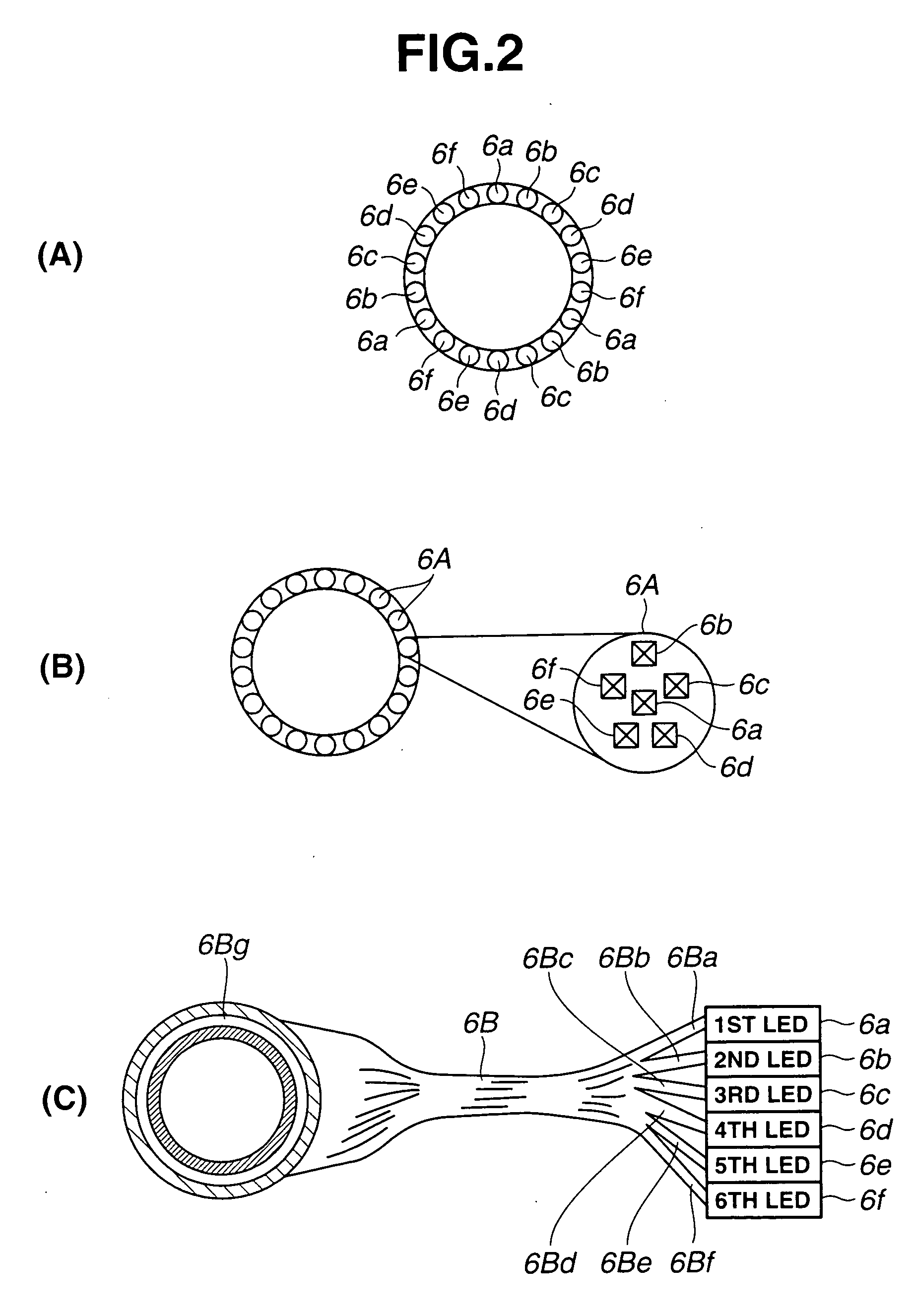
[0205] Referring to FIG. 18(A), the “full mode” is a normal mode for sequentially reading all the pixels of all scanning lines of the CCD 8A at the normal speed. Here, the frames include the frame for simultaneously emitting the light of the first LED 6a, the third LED 6c, and the fifth LED 6e, and the frame for simultaneously emitting the light of the second LED 6b, the fourth LED 6d, and the sixth LED 6f. Means for capturing the six-primary-color image by the above-mentioned light emission will be described later according to the

[0206] As compared with the normal mode shown in FIG. 18(A), the “reading double-speed mode” is a mode for sequentially reading all the pixels of all the scanning lines of the CCD 8A at the double speed of the normal one as shown in FIG. 18(B). Although the reading speed of the double speed is explained as an example, the present invention is not limited to this and may be a proper-multiple time or a variable multiple time.

[0207] The “2 / 4 line double-spee...


PUM


Abstract

An image processing system is used for dentistry. Upon creating a false tooth of a patient (59), a plurality of illuminating light of LEDs with different wavelengths emit light and a photographing apparatus (1A) photographs a tooth portion of the patient (59), thereby obtaining image data. The image data is sent to a dentistry filing system (2A) serving as a processing apparatus, and color reproducing data is obtained by calculation. The color reproducing data is sent to a dentistry factory (55) via a public line. Data is searched from a database (56) for calculating a ceramic compounding ratio, compound data of the ceramic false tooth is obtained, matching the color of the tooth portion of the patient (59), and the false tooth approximate to the tooth color of the patient (59) is created.

Description

TECHNICAL FIELD [0001] The present invention relates to an image processing system, and more particularly, to an image processing system which captures spectroscopic spectrum image information of a subject, and reproduces the color of the subject image from the captured image at high fidelity level, performs inspection or determines the subject image. BACKGROUND ART [0002] Recently, the increase in concern over the beautification and health is confirmed. For the purpose of beatification, the demand for whitening is increased. Conventionally, a camera system for skin check is used for diagnosis in the dermatology, esthetic salon, beauty counseling, and the like. In the dermatology among them, the peculiarity of the skin surface is checked as the diagnosis thereof based on an image of the crista cutis or sulcus cutis and then the counseling is performed. Japanese Unexamined Patent Application Publication No. 8-149352 and Japanese Unexamined Patent Application Publication No. 7-322103 ...

Claims


Application Information

Patent Timeline
Patent Type & Authority Applications(United States)
IPC IPC(8): H04N5/225H04N9/04G06K9/00A61B5/00A61B5/02A61C13/00A61C13/08G01J3/02G01J3/10G01J3/50
CPCA61B5/0088A61B5/02A61C13/0004A61C13/082G01J3/02G01J3/0218G01J3/0224G01J3/0262G01J3/0264G01J3/0272G01J3/0291G01J3/10G01J3/32G01J3/463G01J3/50G01J3/501G01J3/508G01J3/51G01J3/513G01J3/524H04N5/2256H04N9/045H04N2209/043H04N2209/044A61B5/0013H04N13/15H04N23/56H04N23/651H04N23/63H04N23/84H04N25/134A61B5/00
Inventor KOMIYA, YASUHIROWADA, TORUKONNO, OSAMUAJITO, TAKEYUKINAKAMURA, TOMOYUKI
Owner OLYMPUS CORP
Why Eureka
Try Eureka