Variable Magnification Lens Having Image Stabilizing Function

a magnification lens and variable magnification technology, applied in the field of optical equipment, can solve the problems of reducing the size of the optical apparatus, affecting the quality of the image thus obtained, and the electronic image shake correction function also has a similar problem to the optical image shake correction function, so as to reduce the luminance difference, improve the quality, and reduce the effect of luminance variation

Inactive Publication Date: 2006-07-13
CANON KK
View PDF26 Cites 14 Cited by
  • Summary
  • Abstract
  • Description
  • Claims
  • Application Information

AI Technical Summary

Benefits of technology

[0011] The invention is directed to the solution of the prior art described above. It is, therefore, an object of the invention to provide an optical apparatus arranged to be capable of giving an easily viewable-image of high quality by alleviating luminance variations which occur in the peripheral parts of an image plane in correcting image shakes and by lessening a luminance difference between central and peripheral parts of the image plane, particularly at a part in the neighborhood of a telephoto end position where the variations of luminance become conspicuous.

Problems solved by technology

Therefore, the arrangement for having the variable angle prism 100 in that position is disadvantageous in respect of reduction in size of the optical apparatus.
As a result, the quality of an image thus obtained degrades to an unacceptable degree.
Further, the electronic image shake correcting function also has a problem similar to that of the optical image shake correcting function.

Method used


Image

  • Variable Magnification Lens Having Image Stabilizing Function
  • Variable Magnification Lens Having Image Stabilizing Function
  • Variable Magnification Lens Having Image Stabilizing Function

Examples


first embodiment

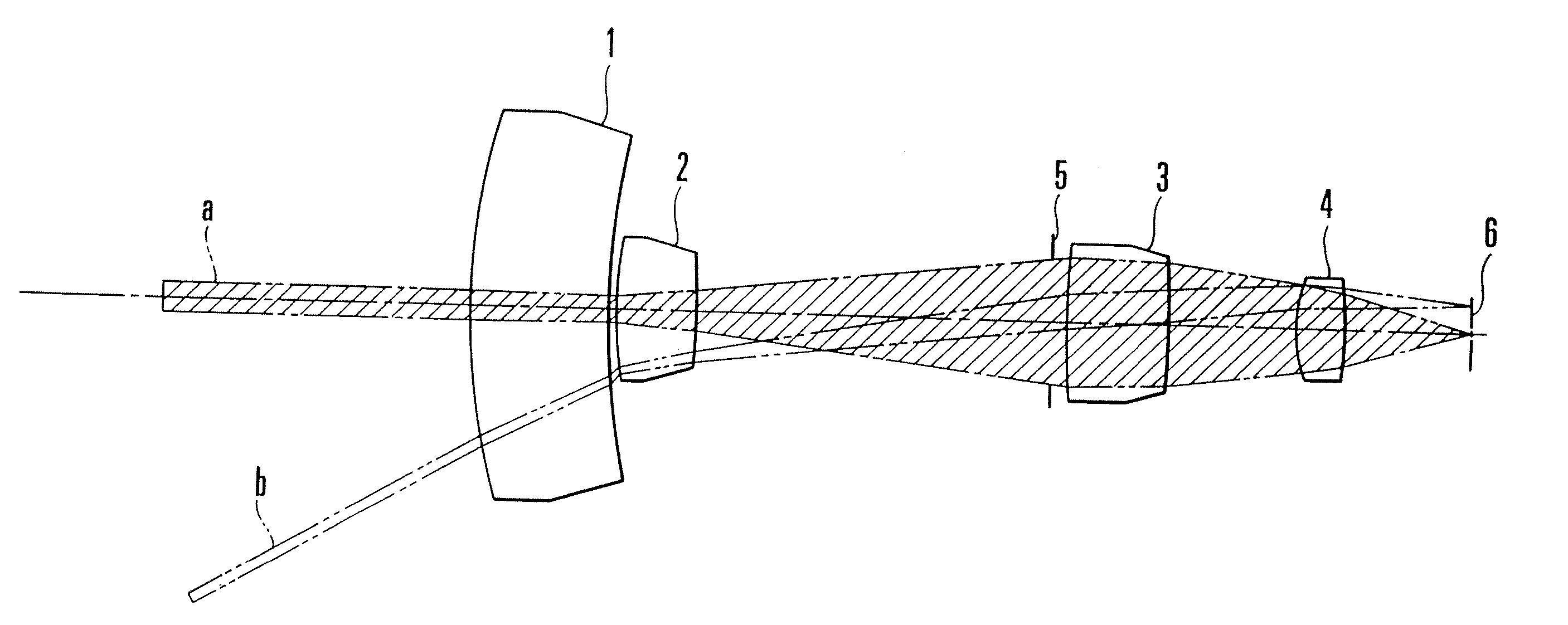
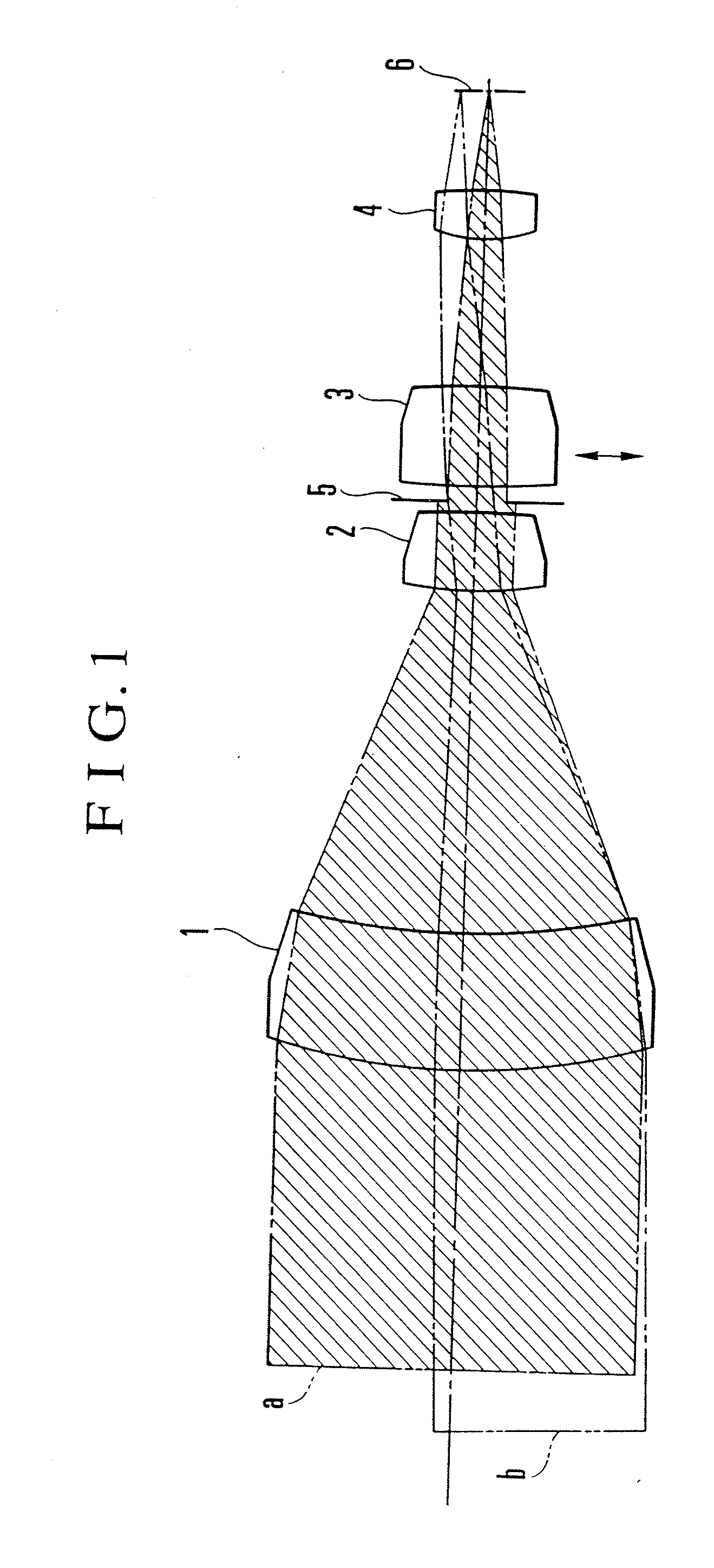
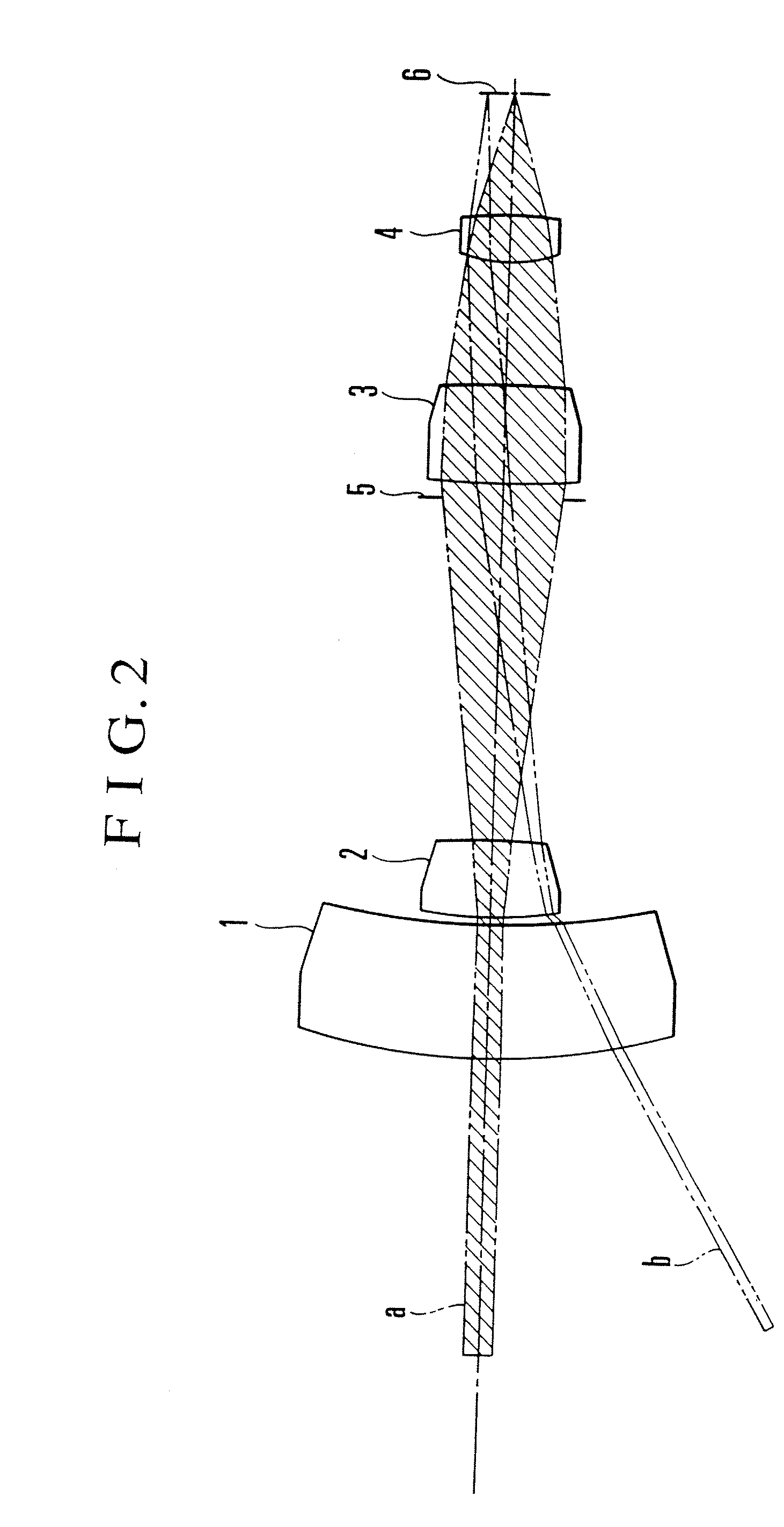
[0044]FIGS. 1 and 2 show a variable magnification optical system having an image shake correcting function according to the invention. The variable magnification optical system is composed of lens units 1 to 4 having positive, negative, positive and positive refracting powers, respectively. In FIG. 1, the variable magnification optical system is shown as in a state obtained with the optical system at a telephoto end position. FIG. 2 shows the variable magnification optical system as in a state obtained with the optical system at a wide-angle end position. The lens unit 1 is a fixed lens unit. The lens unit 2 is a variator lens unit which is provided for varying the magnification of the optical system by moving backward and forward. The lens unit 3 is an image-shake correcting lens unit which is arranged to deflect a light flux by moving (shifting) in a direction perpendicular to an optical axis. The lens unit 4 is a focusing lens unit provided for adjusting focus of the variable mag...

second embodiment

[0064] the invention, which is a more concrete example, is next described below.

[0065]FIG. 11 is a sectional view showing essential parts of a zoom lens (barrel) for a video camera to which the invention is applied as the second embodiment. FIG. 12 is an exploded perspective view showing in part the zoom lens barrel shown in FIG. 11.

[0066] Referring to FIGS. 11 and 12, a fixed tube 201 is arranged to hold a first lens unit L1. A rear tube 202 is arranged to hold a low-pass filter 203. A CCD image sensor which is not shown is mounted in rear of the low-pass filter 203. An image shake correcting unit 204 is arranged to hold a third lens unit L3 which is arranged as a correction lens to be driven in a direction perpendicular to an optical axis. The image shake correcting unit 204 is interposed in between the fixed tube 1 and the rear tube 2 and is fixed in position with screws. A second lens tube 205 is arranged to hold a second lens unit L2 which is provided for zooming. Two guide ba...

third embodiment

[0097]FIG. 20 is an exploded perspective view of the As shown in FIG. 20, the front side of the end face cam 501b of the second lens tube 501 is in a shape which greatly protrudes forward. Therefore, the ring 852 comes to rotate against the urging force of the spring 853 to reduce the size of aperture formed by the blades 820 accordingly as the second lens tube 501 moves rearward, i.e., toward the telephoto end.

[0098] Since the arrangement of the third embodiment obviates the necessity of using an actuator for driving the blades, unlike in the case of the second embodiment, the third embodiment can be more simply arranged and also contributes to reduction in electric energy consumption.

[0099] While the third embodiment uses a moving coil type actuator for driving the correction lens, the same advantageous effect can be attained by replacing this actuator with a motor or an electrostrictive element or some other electromagnetic actuator.

[0100] Further, to have an aperture shape cl...


PUM


Abstract

An image stabilizer for stabilizing an image against unexpected vibrations or shaking of a zoom lens includes a diaphragm arranged to vary its full-open aperture diameter according to a magnification varying (zooming) action from a wide-angle end position to a telephoto end position of the zoom lens for the purpose of preventing variations in light quantity which more conspicuously take place in the peripheral part than in the central part of an image plane when an image stabilizing action is performed.

Description

BACKGROUND OF THE INVENTION [0001] 1. Field of the Invention [0002] The present invention relates to an optical apparatus having a function of correcting image shakes caused by changes of relative angles of an object to be photographed and the optical apparatus. [0003] 2. Description of Related Art [0004] Optical apparatuses of the kind arranged to be capable of correcting image shakes have heretofore been developed in varied manners. FIG. 7 shows an example of such optical apparatuses. In the case of the optical apparatus shown in FIG. 7, the so-called variable angle prism 100 is arranged in front of an optical system composed of lens units 101 to 104 and a diaphragm 105 to correct the image shakes before a light flux P from an object comes to be incident on the optical system. Referring to FIG. 7, the lens units 101 to 104 and the diaphragm 105 are supported by a fixed tube 105. An image sensor 107 is arranged to convert into an electrical signal an optical image formed on a focal...

Claims


Application Information

Patent Timeline
Patent Type & Authority Applications(United States)
IPC IPC(8): G02B27/64G02B15/173
CPCG02B15/173G02B27/646G02B15/144113
Inventor NOGUCHI, KAZUHIROOKADA, TADANORI
Owner CANON KK
Why Eureka
Try Eureka