
Segment-based encoding system using residue coding by basis function coefficients

a coding system and residue technology, applied in the field of segment-based encoding systems, can solve the problems of fractal compression not being a viable general compression method, jpeg and similar compression schemes not addressing the crucial issue of temporal redundancy, and fractal compression is very computationally intensiv

Inactive Publication Date: 2006-07-13
ALTERA CORP
View PDF25 Cites 21 Cited by
  • Summary
  • Abstract
  • Description
  • Claims
  • Application Information

AI Technical Summary

Problems solved by technology

However, JPEG and similar compression schemes do not address the crucial issue of temporal redundancy.
Unfortunately, fractal compression is not a viable method of general compression.
In addition, fractal compression is very computationally intensive.
Although state of the art, block matching is highly inefficient and fails to take advantage of the known general physical characteristics or other information inherent in the images.
However, since blocks do not correspond to real objects, block-based systems cannot use this information to further reduce the bitstream.
Yet another major limitation of block-based matches arises because the residue created by block-based matching is generally noisy and patchy.
Thus, block-based residues do not lend themselves to good compression via standard image compression schemes such as DCT, wavelets, or fractals.
It is well recognized that the state of the art needs improvement, specifically in that the block-based method is extremely inefficient and does not produce an optimally compressed bitstream for motion video information.
While some compression gains are achieved, the associated overhead information is substantially increased because, in addition to the motion and residue information, these schemes require that structural or shape information for each object in a frame must also be sent to the receiver.

Method used


Image

  • Segment-based encoding system using residue coding by basis function coefficients
  • Segment-based encoding system using residue coding by basis function coefficients
  • Segment-based encoding system using residue coding by basis function coefficients

Examples


Embodiment Construction

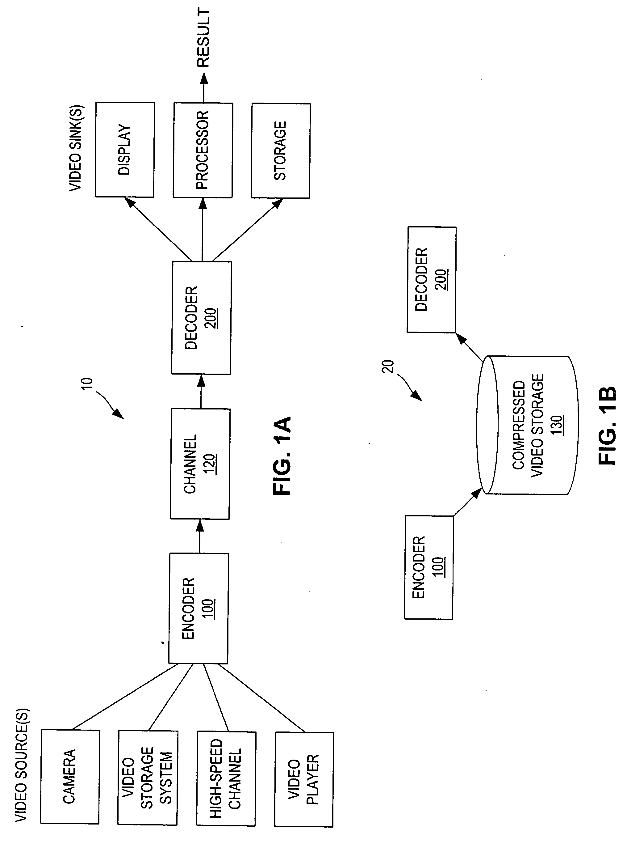
[0034]FIG. 1 is a block diagram of a video stream processing system 10. System 10 accepts video data from any number of sources, encodes it using encoder 100 such that the video data is compressed (i.e., occupies fewer bits than the uncompressed video data) for transport or storage. System 10 includes a decoder 200 that receives the transported or stored compressed video data and decompresses for use by any number of video sinks (users).

[0035] Merely by way of example, possible video sources include a video camera, a video storage system (typically storing uncompressed, or partially compressed, video data), a high-speed channel, such as a cable link or broadcast link capable of transmitting uncompressed or partially compressed video data, or a video player, such as a VCR or DVD player. Possible video users, for example, might include a display device, such as a monitor or television, a video processor or video storage that can store decoded video data.

[0036]FIG. 1(a) illustrates a...


PUM


Abstract

An encoding system includes an encoder that encodes uncompressed video data to form compressed video data and a decoder that decodes the compressed video data to form at least an approximation of the uncompressed video data. The video data comprises a sequence of a plurality of image frames comprising key frames and nonkey frames. In encoding a nonkey frame, reference is made to segments of a reference frame. Kinetic information, such as motion vectors, relates portions of the nonkey frame to the segments of it reference frame. The information content of the nonkey frame that is not conveyed by the segmentation, the reference frame content and the kinetic information can be encoded as residue data. Each segment's residue data, or the nonkey frame's residue data, can be encoded as coefficients of basis functions known to both the encoder and the decoder.

Description

CROSS-REFERENCES TO RELATED APPLICATIONS [0001] This application is a continuation of U.S. application Ser. No. 10 / 338,087, filed on Jan. 6, 2003. U.S. application Ser. No. 10 / 338,087 is a continuation-in-part of U.S. application Ser No. 09 / 550,705, filed on Apr. 17, 2000. U.S. application Ser. No. 09 / 550,705 is a non-provisional of and claims priority from U.S. Provisional Application No. 60 / 129,854, filed on Apr. 17, 1999 and U.S. Provisional Application No. 60 / 129,853, filed on Apr. 17, 1999. The complete disclosures of these applications are incorporated herein by reference.FIELD OF THE INVENTION [0002] The present invention relates generally to the compression of video data, and more particularly to a synchronized encoder / decoder system wherein the decoder performs a segmentation that is performed by the encoder for encoding video data so that the encoder need not convey to the decoder the entire results of the encoder's segmentation. BACKGROUND OF THE INVENTION 1. Brief Intro...

Claims


Application Information

Patent Timeline
Patent Type & Authority Applications(United States)
IPC IPC(8): H04N11/02H04N11/04H04N5/14H04N9/64H04N7/12H04B1/66H04N7/26H04N7/36H04N7/46H04N7/50
CPCG06T9/001H04N19/59H04N19/70H04N19/172H04N19/46H04N19/51H04N19/196H04N19/61H04N19/107H04N19/12H04N19/156H04N19/17H04N19/80H04N19/20H04N19/23H04N19/527H04N19/517H04N19/507H04N19/52
Inventor PRAKASH, ADITYOFODOR, ENIKO
Owner ALTERA CORP
Learn More