Molecular dynamics measurement device and method based on quantum coherence control

A molecular dynamics and quantum coherence technology, applied in the measurement of color/spectral properties, material excitation analysis, etc., and can solve difficult problems

Active Publication Date: 2019-04-16
SUN YAT SEN UNIV
View PDF3 Cites 7 Cited by
  • Summary
  • Abstract
  • Description
  • Claims
  • Application Information

AI Technical Summary

Problems solved by technology

[0003] However, the above research can only obtain a static branching ratio optimal value at present, but how d

Method used


Image

  • Molecular dynamics measurement device and method based on quantum coherence control
  • Molecular dynamics measurement device and method based on quantum coherence control
  • Molecular dynamics measurement device and method based on quantum coherence control

Examples


Embodiment 1

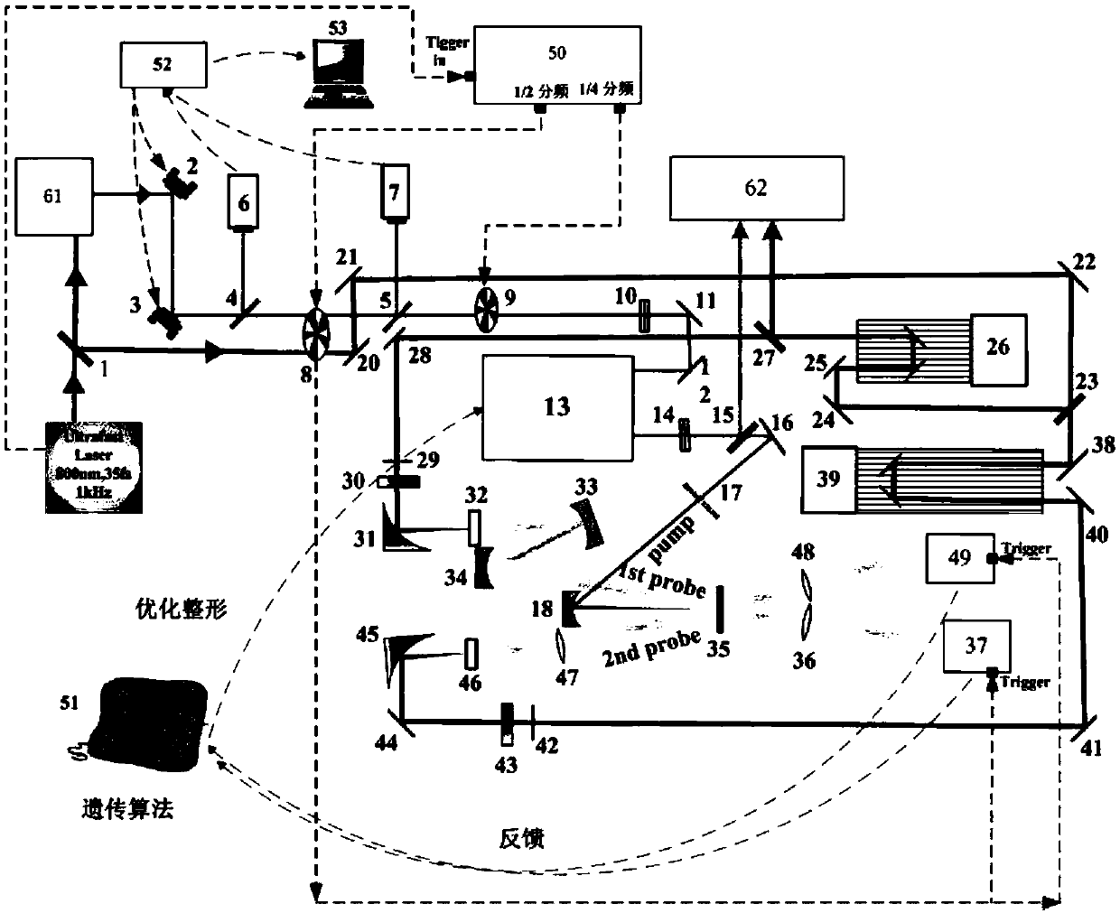
[0051] Such as figure 1 As shown, a molecular dynamics measurement device based on quantum coherence control in the present invention specifically includes a femtosecond laser light source, a beam splitter 1, a pump optical path system, a femtosecond pulse shaper 13, a detection optical path system and a first computer 51, The beam splitter 1 divides the femtosecond laser light generated by the femtosecond laser light source into pump light and probe light;

[0052] The pump optical path system is connected with the femtosecond pulse shaper 13, and is used to excite the chemical sample after the pump light enters the femtosecond pulse shaper 13 for shaping;

[0053] The detection optical path system includes a first beam splitter 23, a first detection optical path and a second detection optical path. The detection light is divided into two beams of detection light by the first beam splitter 23, and one detection light passes through the first detection optical path to form super...

Embodiment 2

[0074] The molecular dynamics measurement method based on quantum coherence control in this embodiment is basically the same as that in Embodiment 1, the difference lies in a molecular dynamics measurement device based on quantum coherence control, such as figure 1 As shown, using 800nm, 35fs, 1kHz femtosecond laser as the fundamental frequency light source, the beam splitter 1 is first divided into two parts: the pumping optical path system and the detection optical path system, in which the light source of the pumping optical path system is incident by the 800nm ​​femtosecond laser The optical parametric amplifier 61 (OPA) generates tunable visible light femtosecond pulses, and then the pump light passes through the optical path stabilization system, and is chopped into 250 Hz femtosecond pulses by the first chopper 8 and the second chopper 9 The light then passes through the polarizer 10, the third mirror 11, and the fourth mirror 12, enters the femtosecond pulse shaper 13 f...


PUM


Abstract

The invention provides a molecular dynamics measurement device and method based on quantum coherence control. The molecular dynamics measurement device comprises a femtosecond laser light source, a beam splitter, a pump light path system, a femtosecond pulse shaper, a detection light path system, a computer and a pulse measuring system, wherein the beam splitter is used for dividing the femtosecond laser into pump light and detection light; the pumping light path system enables pumping light to enter the femtosecond pulse shaper and then excite the chemical sample; the detection light path system is used for collecting transient absorption spectrum signals of a first excitation single state and a first excitation triplet state of the chemical sample; and the pulse measuring system is composed of a beam splitting sheet and a spatial encoding type spectral phase coherent direct electric field reconstruction method. The molecular dynamics measurement device is capable of combining the quantum coherence regulation and controlling, the pumping detection technology and the pulse measuring technology, the branch ratio of different light excitation relaxation products can be changed by optimizing the laser pulses, the dynamics information of the whole spectrum detected is analyzed under different shape pulses, and the information obtained by the pumping detection technology is greatlyenriched.

Description

technical field [0001] The invention relates to the technical field of molecular reaction dynamics, in particular to a quantum coherent control-based molecular dynamics measurement method and a device thereof. Background technique [0002] In 1986, P.Brumer and M.Shapiro proposed the quantum coherent control technology for the first time in theory, and it was confirmed by R.J.Gordon et al. in the experiment of molecular system (HCl) in 1991. Since then, due to the wide application of femtosecond lasers, quantum coherence control technology has been developed rapidly, and has been widely used in the control of chemical reactions, high-field laser ionization, high-order harmonics and the generation of attosecond pulses. As far as chemical reactions are concerned, quantum coherence control technology usually uses a programmable spatial light modulator (SLM) to modulate the intensity and phase of each spectral component of the pulse to achieve femtosecond pulse shaping, and then...

Claims


Application Information

Patent Timeline
IPC IPC(8): G01N21/63G01N21/39
CPCG01N21/39G01N21/63
Inventor 张蕾赵芳
Owner SUN YAT SEN UNIV
Why Eureka
Try Eureka