
Electro-mechanical system and method for mixing replenishment for plate precursor developers

a technology of precursors and electromechanical systems, applied in the field of lithographic printing, can solve the problems of depletion of active solvents or dispersing agents, changes in developer activity, and loss of developer volum

Inactive Publication Date: 2006-07-13
EASTMAN KODAK CO
View PDF9 Cites 10 Cited by
  • Summary
  • Abstract
  • Description
  • Claims
  • Application Information

AI Technical Summary

Benefits of technology

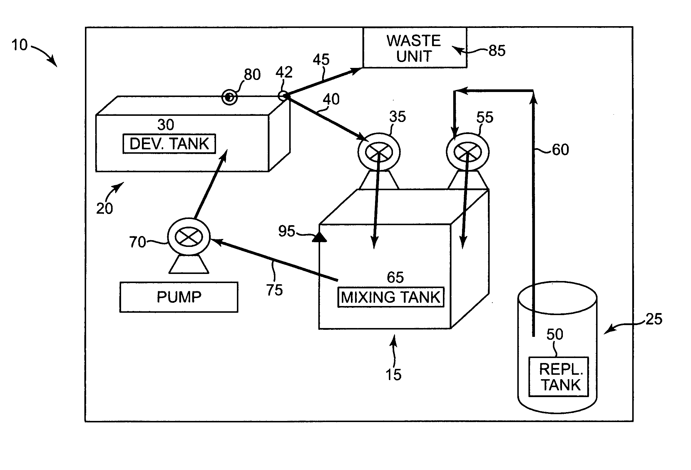
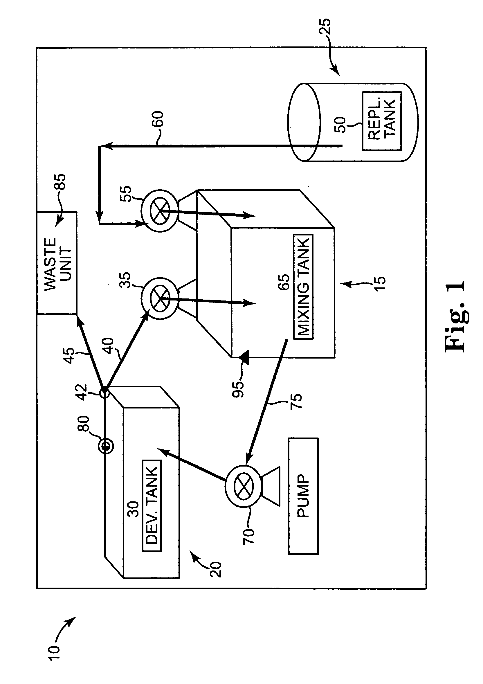
The invention is a system for replenishing a lithographic printing plate developer. It includes a developer unit with a seasoned developer and a replenisher unit with a replenisher. The mixing unit holds a mixture of an equal volume of replenisher and seasoned developer, which is then delivered to the developer unit. The developer unit applies the seasoned developer to printing plate precursors. The system also includes sensors to monitor developer activity. The technical effect of the invention is to provide a system for efficiently replenishing a developer system with a mixture of seasoned developer and replenisher.

Problems solved by technology

In one example, the concentration of the active solvent or the dispersing agent may become depleted.
Changes in developer activity may be caused by loss of developer volume as printing plates carry developer out of the developer apparatus.
Additionally, interactions with the radiation-sensitive coatings of the printing plate precursors may also affect developer activity.
This loss of developer activity may result in inconsistency in overall dot density over a cycle of developed printing plates, which may have adverse effects during printing.
Measuring the electrical conductivity does not therefore allow a conclusion on the efficiency or activity of the developer in every case.
Constant or unchanging conductivity values therefore do not guarantee the developer activity required for the desired consistent developing results.
However, this system requires an expensive computer-controlled system.

Method used


Image

  • Electro-mechanical system and method for mixing replenishment for plate precursor developers
  • Electro-mechanical system and method for mixing replenishment for plate precursor developers
  • Electro-mechanical system and method for mixing replenishment for plate precursor developers

Examples


example 1

Change in conductivity and Fog Point

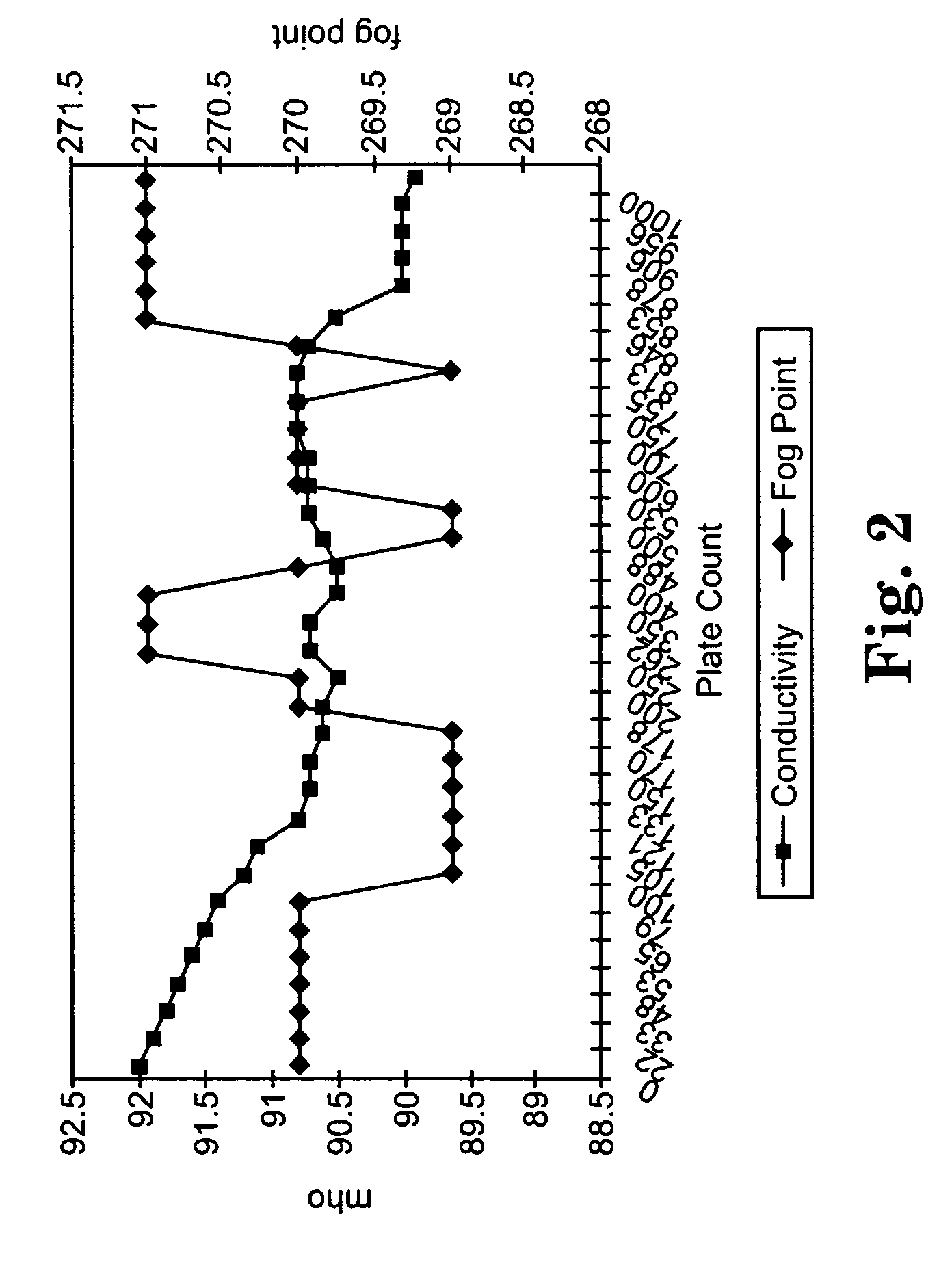
[0042] Change in fog point and conductivity was determined over the course of 1000 printing plate precursors using the MX1813 developer replenished with MX1919. A 1:1 ratio of the seasoned developer and replenisher was added after every plate developed. The fog point and preheat oven operating temperature was first determined as described above. The conductivity measurement in ohms was determined with a processor on-board conductivity meter with ATC.

[0043] The data shown in FIG. 2 demonstrated that when the MX1919 replenisher was used the fog point shift was within approximately a 2° F. change. The normal fog point shift from start to the end of a cycle using only developer was an approximately 3° F. downward shift, as shown in Table 1.

[0044]FIG. 2 demonstrated that the developer conductivity dropped by 2 to 3 conductivity points during the course of the 1000-plate precursor cycle compared to the a system when only developer was used (see Table...

example 2

Mix Ratio Testing

[0045] The exposure conditions as detailed above were repeated and developed using the ratios of replenisher to seasoned developer as shown in Table 2. The original developer, MX1813 was replenished with MX1919. The conductivity readings (ohms) were monitored using a processor on-board conductivity meter with ATC. The results are shown in Table 2.

TABLE 2Plate Count3:11:11:30929292.52291.991.991.93391.991.891.74891.891.791.35391.891.690.96591.791.590.77991.691.490.510091.691.290.410591.491.190.112190.990.890.113390.790.789.915090.790.789.717090.690.689.417890.690.689.420090.590.589.325090.790.789.126290.790.788.835090.690.588.840090.690.588.548890.690.688.350090.790.788.353090.790.788.360090.790.788.270090.890.887.875090.890.88680090.890.885.485090.790.785.390090.590.585.2100090.59085.1

[0046] The data shown in Table 2 demonstrated that the use of a 1:1 replenisher to seasoned developer is effective in maintaining the developer conductivity during the course of the...


PUM

PropertyMeasurementUnit
temperatureaaaaaaaaaa

Abstract

The present invention provides a system and method for replenishing a lithographic printing plate developer. The system includes a developer unit containing a seasoned developer and adapted to deliver the seasoned developer into a mixing unit, a replenisher unit containing a replenisher and adapted to deliver the replenisher into the mixing unit, and the mixing unit is in fluid communication with the developer unit and the replenisher unit and is adapted to hold a mixture of an equal volume of the replenisher and the seasoned developer. The mixture of an equal volume of the replenisher and the seasoned developer is then delivered to the developer unit.

Description

BACKGROUND [0001] The art of lithographic printing is based on the immiscibility of ink and water. A lithographic printing plate is composed of ink receptive regions, commonly referred to as the “image area,” and hydrophilic regions. When the surface of the printing plate is moistened with water and printing ink is applied, the hydrophilic regions retain the water and repel the printing ink, and the image area retains the printing ink and repels the water. The printing ink retained on the image area may then be transferred to the surface of a material upon which the image is to be reproduced. Typically, the ink is first transferred to an intermediate blanket, which in turn transfers the ink to the desired surface. [0002] Lithographic printing plate precursors typically include a radiation-sensitive coating applied over the hydrophilic surface of a substrate. Conventional radiation-sensitive coatings include photosensitive components dispersed within an organic polymeric binder. Afte...

Claims


Application Information

Patent Timeline
Patent Type & Authority Applications(United States)
IPC IPC(8): G03C5/18
CPCG03F7/3071
Inventor GINTHER, DEAN
Owner EASTMAN KODAK CO
Learn More