
Method for preparation of lithographic printing plate and lithographic printing plate precursor

a technology of lithographic printing plate and precursor, which is applied in the field of preparation of lithographic printing plate and lithographic printing plate precursor, can solve the problems of deficiency of water resistance and film strength of the photosensitive layer hardened with exposure, and achieve excellent safelight aptitude and high sensitivity

Inactive Publication Date: 2007-01-25
FUJIFILM CORP +1
View PDF16 Cites 63 Cited by
  • Summary
  • Abstract
  • Description
  • Claims
  • Application Information

AI Technical Summary

Benefits of technology

The present invention provides a method for making a lithographic printing plate using an aqueous developer with pH of 2.0 to 10.0. The method involves exposing a lithographic printing plate precursor to a laser beam and using a hexaarylbiimidazole compound as an initiator. The photosensitive layer of the precursor is sensitive to the laser and does not form fog under a safelight. The exposed precursor is then rubbed with a developer and a rubbing member to remove the protective layer and an unexposed area of the photosensitive layer. The resulting plate has high sensitivity and is excellent in safelight aptitude. The invention also provides a lithographic printing plate precursor that can be used in this method.

Problems solved by technology

In order to maintain developing property to the aqueous developer having pH of 2.0 to 10.0, however, it is necessary for the photosensitive layer to be hydrophilic or highly water-permeable and thus, but the photosensitive layer hardened with exposure is deficient in water-resistance and film strength.

Method used


Image

  • Method for preparation of lithographic printing plate and lithographic printing plate precursor
  • Method for preparation of lithographic printing plate and lithographic printing plate precursor
  • Method for preparation of lithographic printing plate and lithographic printing plate precursor

Examples


examples

[0255] The present invention will be described in more detail with reference to the following examples, but the invention should not be construed as being limited thereto.

[Preparation of Support 1]

[0256] An aluminum plate (material: 1050) having a thickness of 0.3 mm was subjected to a degrease treatment with an aqueous 10% by weight sodium aluminate solution at 50° C. for 30 seconds to remove rolling oil on the surface thereof. Thereafter, the aluminum plate surface was grained using three nylon brushes implanted with bundled bristles having a diameter of 0.3 mm and an aqueous suspension (specific gravity: 1.1 g / cm3) of pumice having a median diameter of 25 μm, and then thoroughly washed with water. The plate was etched by dipping it in an aqueous 25% by weight sodium hydroxide solution at 45° C. for 9 seconds and after washing with water, dipped in an aqueous 20% by weight nitric acid solution at 60° C. for 20 seconds, followed by washing with water. The etching amount of the gr...

examples 1 to 12

(1) Exposure, Development and Printing

[0283] Each of Lithographic Printing Plate Precursors (1) to (12) was subjected to imagewise exposure using a semiconductor laser of 405 nm having an output of 100 mW while changing energy density.

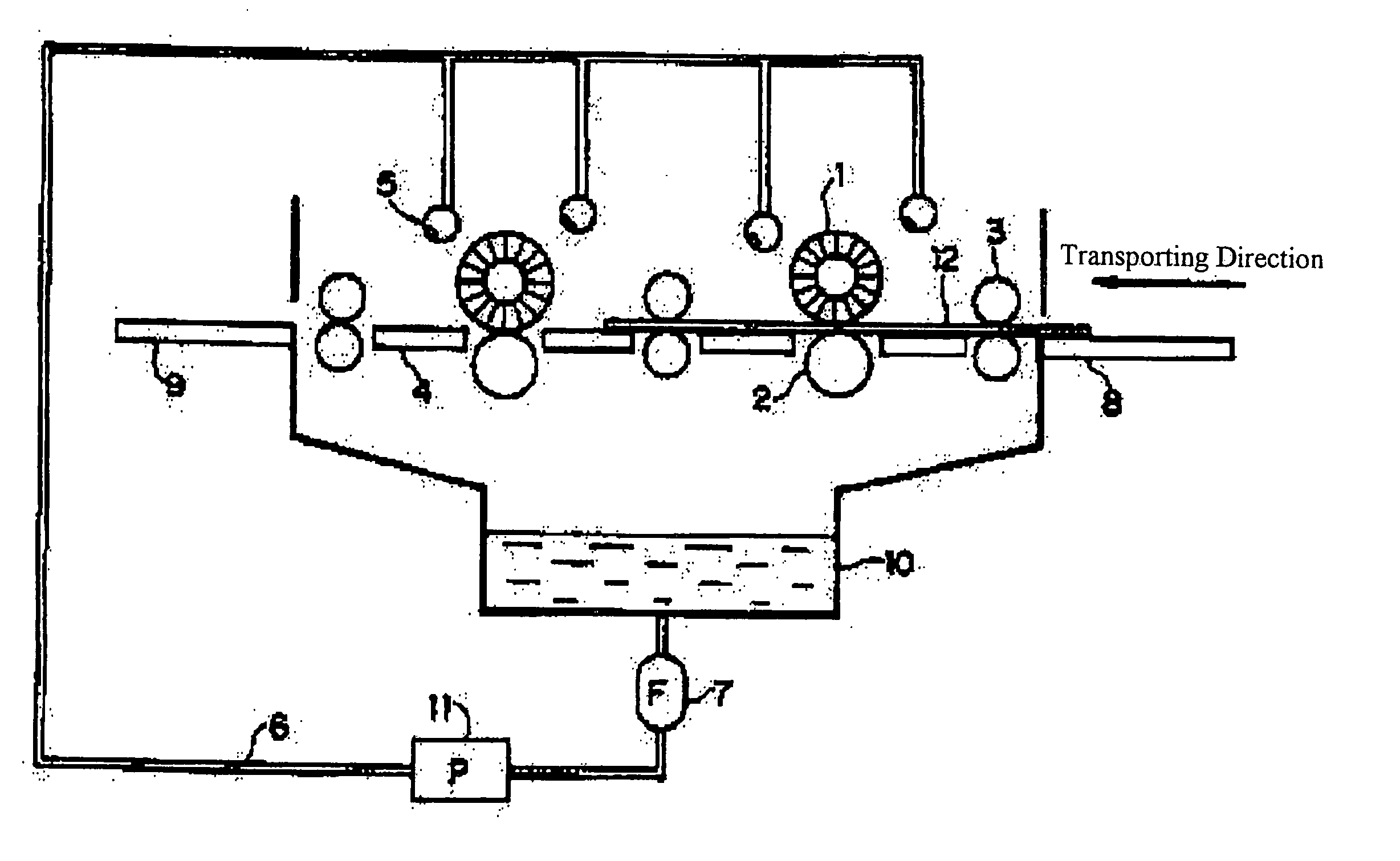
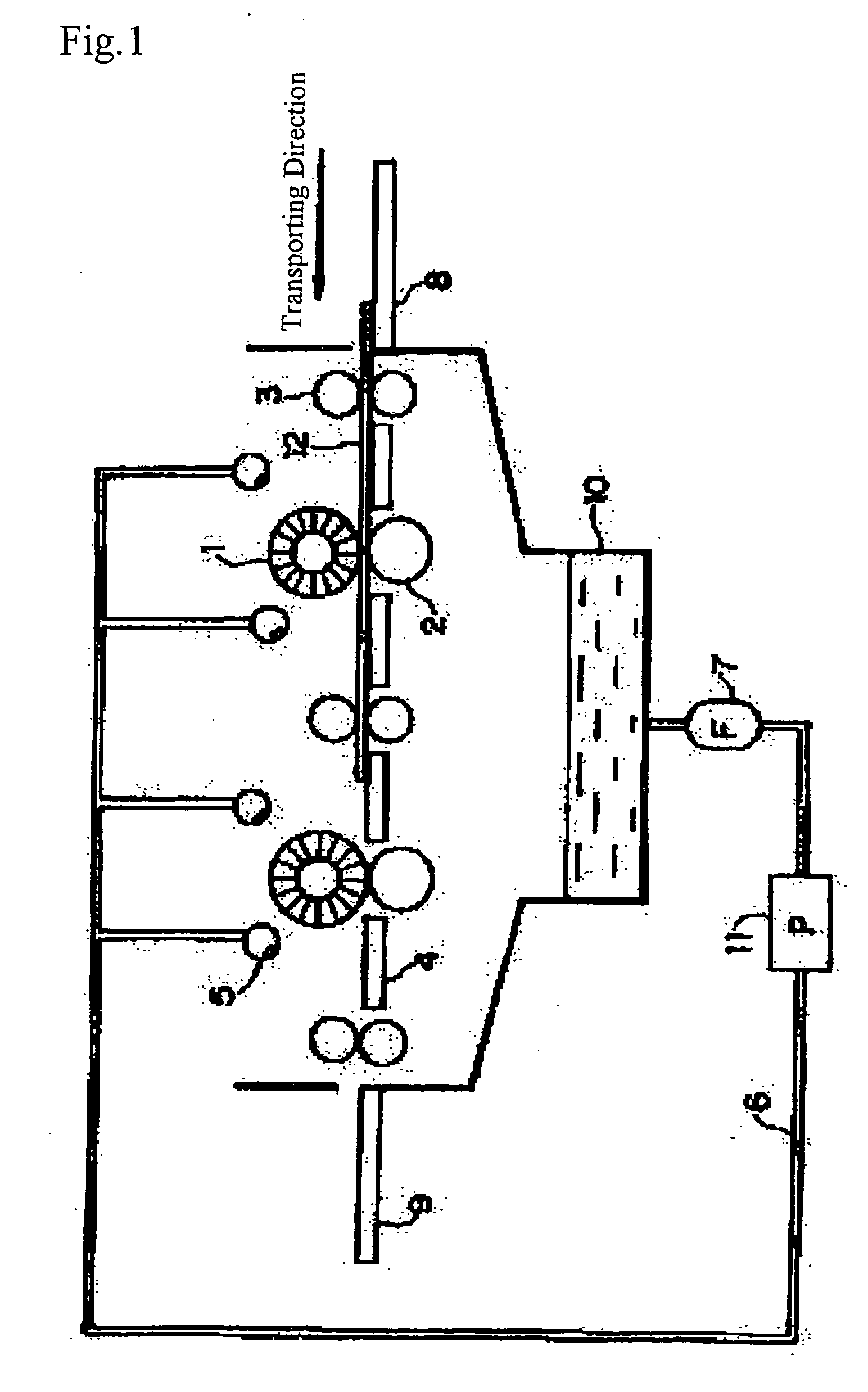
[0284] Then, development processing was performed in an automatic development processor having a structure shown in FIG. 1 using Developer (1) having the composition shown below. The pH of the developer was 5. The automatic development processor was an automatic processor having two rotating brush rollers. As for the rotating brush rollers used, the first brush roller was a brush roller having an outer diameter of 90 mm and being implanted with fiber of polybutylene terephthalate (bristle diameter: 200 μm, bristle length: 17 mm), and the brush roller was rotated at 200 rpm in the same direction as the transporting direction (peripheral velocity at the tip of brush: 0.94 m / sec). The second brush roller was a brush roller having an outer diameter of 6...

examples 13

[0290] The image exposure, development processing and printing were conducted in the same manner as in Example 1 except for changing the polyoxyethylene naphthyl ether used in Developer (1) to an anionic surfactant having the structure shown below and further adding. 0.1 g of a defoaming agent, FS Antifoam DR110N (produced by Dow Corning Corp., silicone-based emulsion). As a result, the evaluation results similar to those in Example 1 were obtained.


PUM

PropertyMeasurementUnit
wavelength rangeaaaaaaaaaa
pHaaaaaaaaaa
pHaaaaaaaaaa

Abstract

A method for preparation of a lithographic printing plate comprising: exposing a lithographic printing plate precursor comprising a hydrophilic support, a photosensitive layer containing (A) a sensitizing dye having an absorption maximum in a wavelength range of from 350 to 450 nm, (B) a hexaarylbiimidazole compound, (C) a polymerizable compound, (D) a hydrophobic binder polymer and (E) a chain transfer agent and a protective layer in this order, with a laser beam of from 350 to 450 nm; and rubbing a surface of the exposed lithographic printing plate precursor with a rubbing member in a presence of a developer having pH of from 2 to 10 in an automatic processor equipped with the rubbing member to remove the protective layer and an unexposed area of the photosensitive layer.

Description

FIELD OF THE INVENTION [0001] The present invention relates to a method for preparation of a lithographic printing plate and a lithographic printing plate precursor for use in the method. BACKGROUND OF THE INVENTION [0002] In general, a lithographic printing plate has a surface composed of an oleophilic image area and a hydrophilic non-image area. Lithographic printing is a printing method comprising supplying alternately dampening water and oily ink on the surface of lithographic printing plate, making the hydrophilic non-image area a dampening water-receptive area (ink unreceptive area) and depositing the oily ink only to the oleophilic image area by utilizing the nature of the dampening water and oily ink to repel with each other, and then transferring the ink to a printing material, for example, paper. [0003] In order to produce the lithographic printing plate, a lithographic printing plate precursor (PS plate) comprising a hydrophilic support having provided thereon an oleophil...

Claims


Application Information

Patent Timeline
Patent Type & Authority Applications(United States)
IPC IPC(8): G03F7/00
CPCG03F7/002G03F7/305G03F7/033G03F7/031G03F7/0388
Inventor INNO, TOSHIFUMI
Owner FUJIFILM CORP
Learn More