
Planographic printing plate material, planographic printing plate, and printing process employing the same

a technology of planographic printing plate and material, which is applied in the direction of lithography, photosensitive materials, instruments, etc., can solve the problems of increasing the cost of the device, reducing the image formation speed, and no proposal of processless plate material having sufficient printing properties, etc., and achieves simple water development and high printing durability.

Inactive Publication Date: 2006-01-26
KONICA MINOLTA MEDICAL & GRAPHICS INC
View PDF12 Cites 70 Cited by
  • Summary
  • Abstract
  • Description
  • Claims
  • Application Information

AI Technical Summary

Benefits of technology

[0010] An object of the invention is to provide a planographic printing plate material, which is subjected to simple water development or is mounted on a plate cylinder of a printing press without any prior development processing to be able to obtain a planographic printing plate, to provide a planographic printing plate with high printing durability, and to provide a printing process employing the planographic printing plate.

Problems solved by technology

There are no proposals of a processless plate material having sufficient printing properties as a versatile printing plate material.
However, in order to employ a printing plate material of this type, it is necessary that a means for removing completely scattered matter produced by ablation of the surface layer be installed in an exposure device used, which results in problem of greatly increasing cost of the device.
Further, since exposure energy necessary to expose is relatively high, it is necessary to lower the scanning speed of exposure beam during exposure (for example, to decrease rate of rotation of an exposure drum), which may lower image formation speed.
Since kinds or amount of components added to the hydrophilic layer are limited in view of providing an anti-stain property, it is difficult to freely control the surface tension or viscosity of a hydrophilic layer coating solution.

Method used


Image

  • Planographic printing plate material, planographic printing plate, and printing process employing the same
  • Planographic printing plate material, planographic printing plate, and printing process employing the same

Examples


example 1

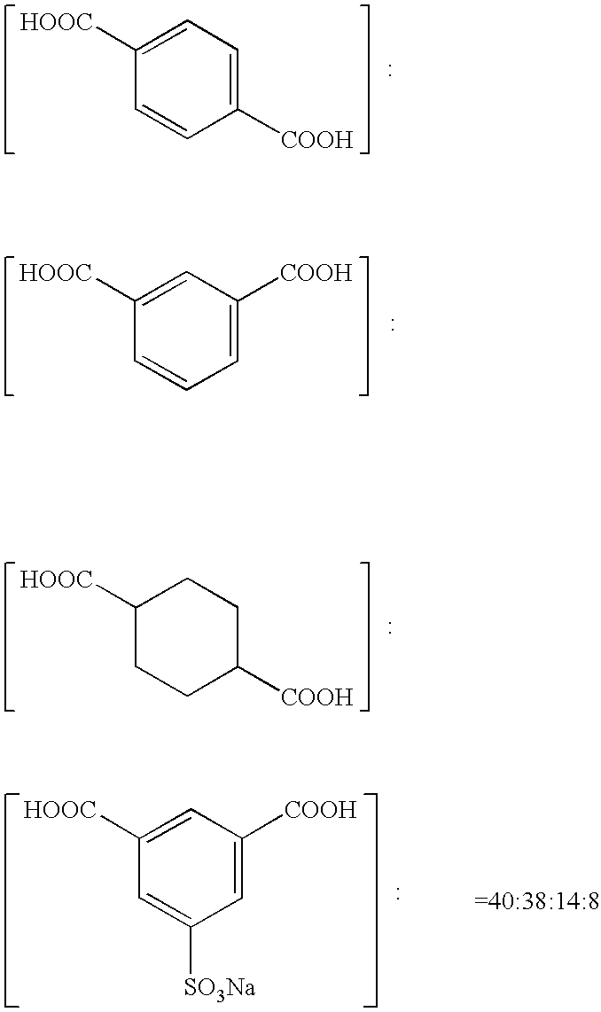
[0148] Employing terephthalic acid and ethylene glycol, PET having an intrinsic viscosity VI of 0.66 (at 25° C. in a phenol / tetrachloroethane (6 / 4 by weight) solvent) was prepared according to a conventional method. The resulting polyethylene terephthalate was formed into pellets, dried at 130° C. for 4 hours, and melted at 300° C. The melted polyethylene terephthalate was extruded from a T-shaped die onto a 50° C. drum, and rapidly cooled. Thus, an unstretched film sheet having an average thickness of 175 μm was obtained. The film sheet was stretched in the mechanical direction at 102° C. by a stretching magnification of 1.3, and then at 110° C. by a stretching magnification of 2.6. Successively, the stretched film sheet was further stretched at 120° C. by a stretching magnification of 4.5 in the transverse direction in a tenter. The resulting sheet was heat fixed at 240° C. for 20 seconds and relaxed at 240° C. in the transverse direction by 4%. Thereafter, the sheet at the chuck ...


PUM


Abstract

Disclosed is a planographic printing plate material comprising a plastic support and provided thereon, a subbing layer containing a water-soluble resin, a hydrophilic layer containing metal oxide particles with an average particle diameter of from 3 to 100 nm, and an image formation layer containing heat melting particles or heat fusible particles in that order, the planographic printing plate material being in the form of roll, wherein a dry coating amount of the water-soluble resin in the subbing layer is in the range of from 0.001 g / m2 to 3.0 g / m2.

Description

[0001] This application is based on Japanese Patent Application No. 2004-212799 filed on Jul. 21, 2004 in Japanese Patent Office, the entire content of which is hereby incorporated by reference. FIELD OF THE INVENTION [0002] The present invention relates to a planographic printing plate material, a planographic printing plate, and a printing process employing the same. BACKGROUND OF THE INVENTION [0003] An inexpensive planographic printing plate material for CTP (Computer to Plate) system, which can be easily handled and has a printing ability comparable with that of PS plates, is required accompanied with the digitization of printing data. Recently, a so-called processless plate material requiring no development due to a specific developer is strongly desired, which can be applied to a printing press (DI printing press) installed with a direct imaging (DI) system. [0004] A processless plate material is considered which employs a grained aluminum plate like that of PS plates. Howeve...

Claims


Application Information

Patent Timeline
IPC IPC(8): G03C1/494
CPCB41C1/1025B41C2201/04B41N1/14B41C2201/06B41C2210/24B41C2201/14B41C2210/04B41C2210/08B41C2210/22B41C2201/10
Inventor MIYOSHI, MASAKI
Owner KONICA MINOLTA MEDICAL & GRAPHICS INC
Learn More