
Grinding machines for depression patterns along roads

a technology of depression pattern and grinding machine, which is applied in the direction of roads, manufacturing tools, roads, etc., can solve the problems of long process, noise and vibration, and the method does not work after the material has set, and achieve the effect of eliminating interference with snowplow operation

Active Publication Date: 2006-07-13
CONEQTEC CORP
View PDF19 Cites 1 Cited by
  • Summary
  • Abstract
  • Description
  • Claims
  • Application Information

AI Technical Summary

Benefits of technology

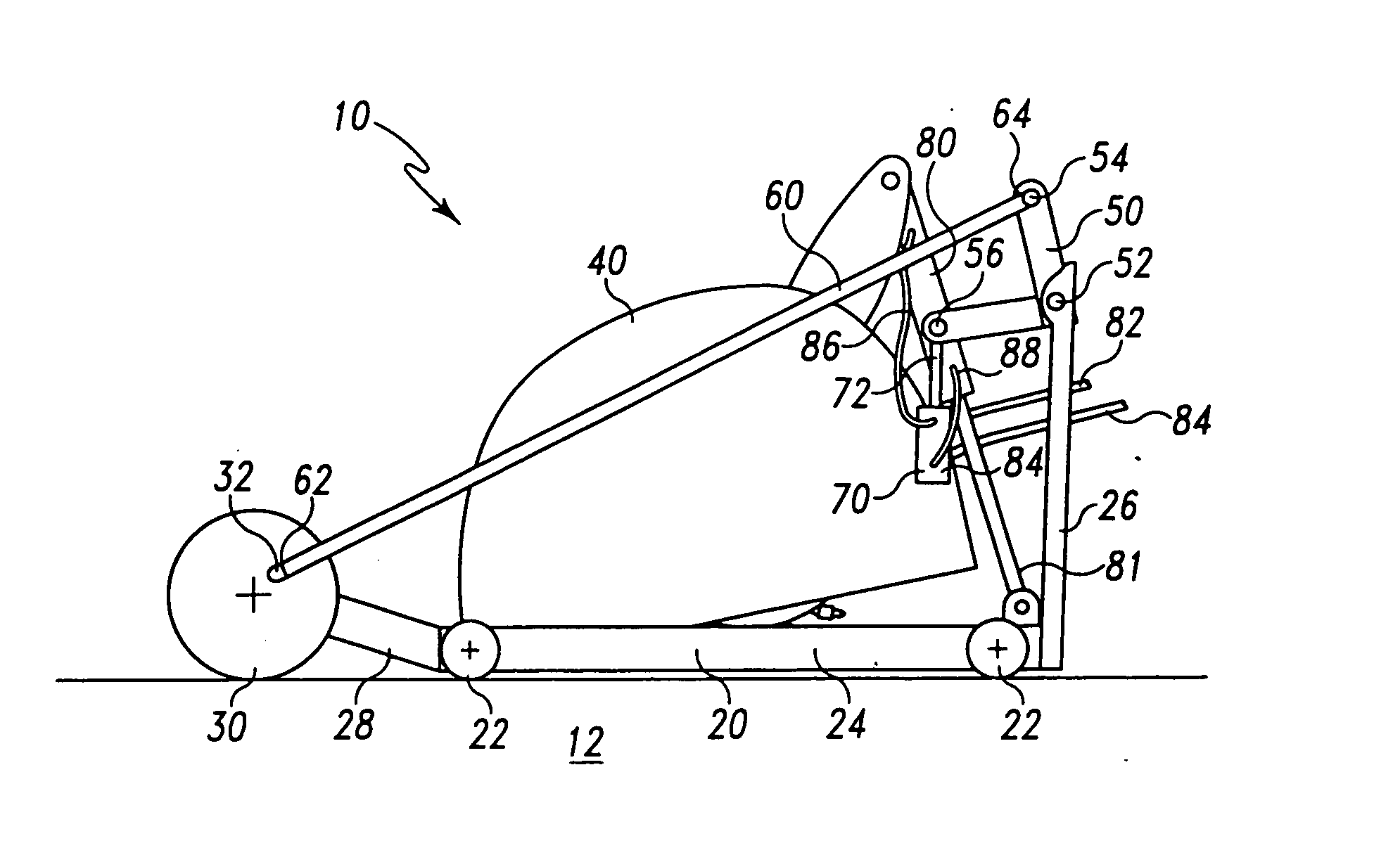
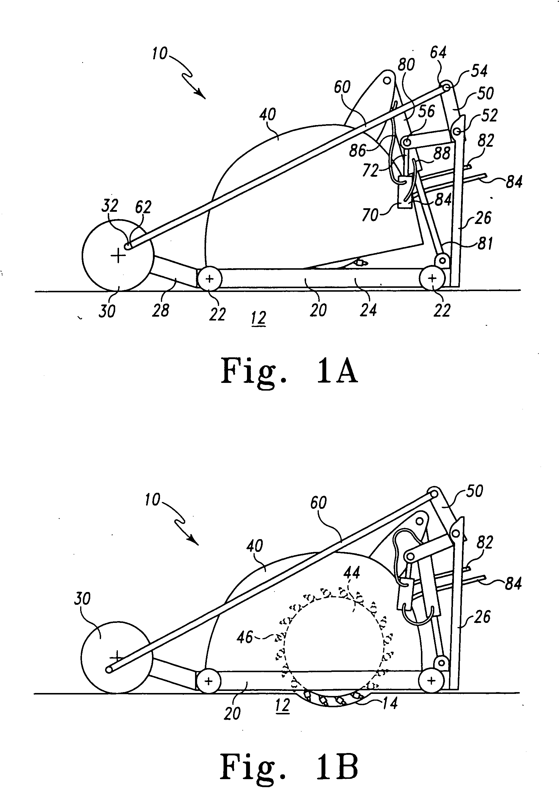
The present invention provides a grinding machine for creating depression patterns in surfaces such as asphalt or concrete. These depression patterns, known as rumble strips, can be used to alert drivers who drift off a driving lane. The use of depression patterns instead of protrusions eliminates interference with snowplow operation in areas where plows are used. The grinding machine is based on a grinding drum associated with a surface following portion, such as a frame or trolley, which typically moves at a uniform height along or above a surface for stable support. A hydraulic control device causes the grinding assembly to be raised and lowered relative to the trolley in a predetermined pattern. The grinding machine can be mounted on a host machine or it can operate independently. The method involves grinding a series of depressions in a surface by moving a gauge wheel along the surface while the grinding assembly raises and lowers relative to the trolley. The raising and lowering is hydraulically controlled. The technical effects of this invention include improved grinding efficiency, reduced interference with snowplow operation, and improved safety for drivers.

Problems solved by technology

These depression patterns interfere with the smooth driving of a vehicle by creating a noise and a vibration when a vehicle encounters the pattern.
This method does not work after the material has set.
This can be a lengthy process and requires precise re-positioning for each new cut.
On less than ideal surfaces, the bearing wheel can slip, causing poor depression spacing.

Method used


Image

  • Grinding machines for depression patterns along roads
  • Grinding machines for depression patterns along roads
  • Grinding machines for depression patterns along roads

Examples


Embodiment Construction

[0020] For the purposes of promoting an understanding of the principles of the invention, reference will now be made to the embodiments illustrated and specific language will be used to describe the same. It will nevertheless be understood that no limitation of the scope of the invention is thereby intended, such alterations, modifications, and further applications of the principles of the invention being contemplated as would normally occur to one skilled in the art to which the invention relates.

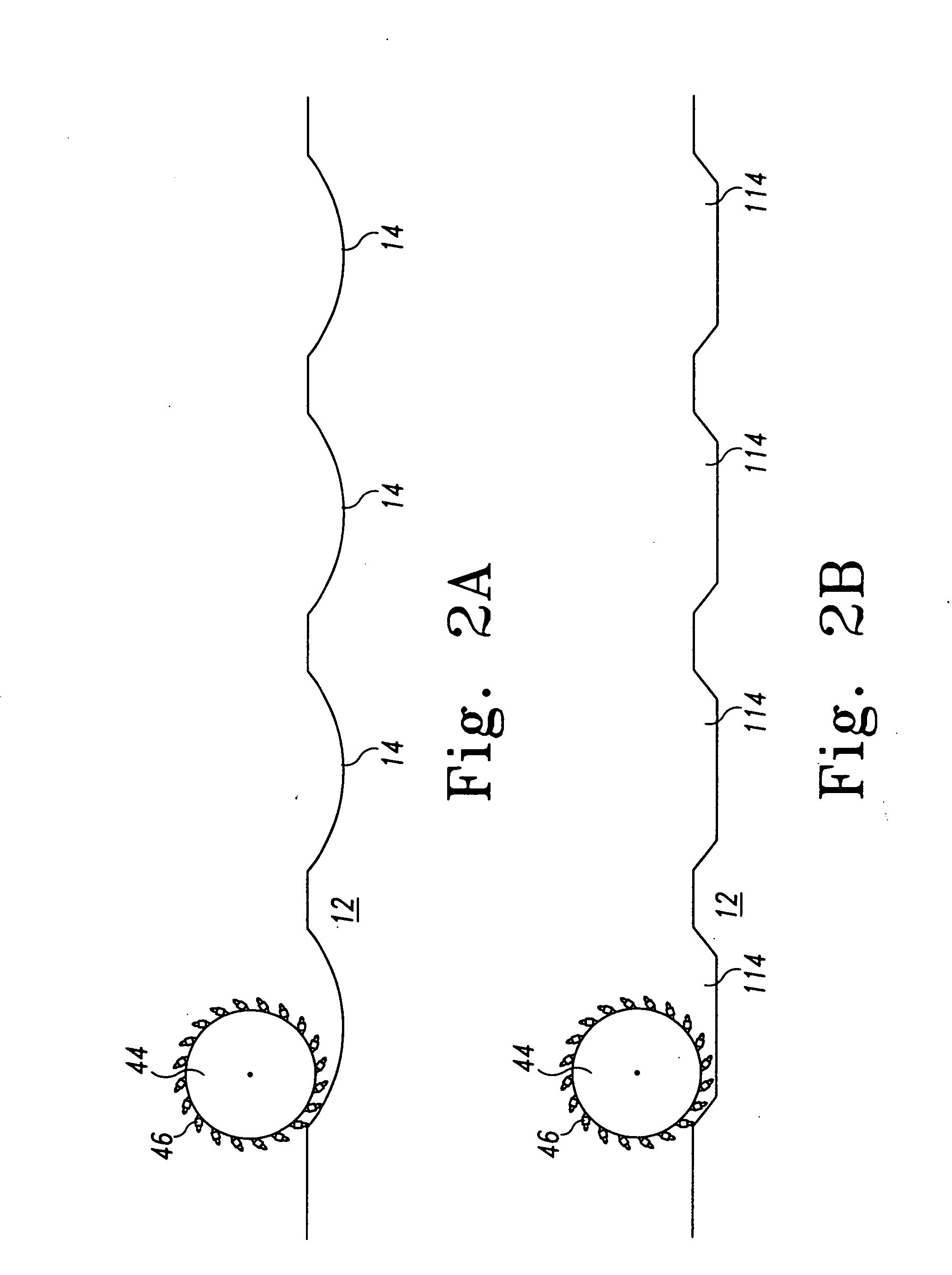
[0021] In certain preferred embodiments, the present invention provides a grinding machine for creating depression patterns in a surface such as asphalt or concrete. The depression pattern may be a rumble strip for alerting drivers who drift off a driving lane, or may be for other uses. Use of a depression pattern (instead of protrusions) eliminates interference with snowplow operation in areas where plows are used. In the present invention, the grinding machine is based on grinding drum ...


PUM


Abstract

In certain preferred embodiments, the present invention provides a grinding machine for creating depression patterns in a surface such as asphalt or concrete. The depression pattern may be a rumble strip for alerting drivers who drift off a driving lane, or may be for other uses. Use of a depression pattern (instead of protrusions) eliminates interference with snowplow operation in areas where plows are used. In the present invention, the grinding machine is based on a trolley which moves at a uniform height along a surface, and includes a forward “gauge” wheel which controls the relative grinding drum depth based on the wheel position and rotation. In a preferred embodiment, the grinding assembly is raised and lowered relative to the trolley in correspondence with the advancement of the trolley.

Description

[0001] This application claims the benefit of provisional application Ser. No. 60 / 449,706 filed on Feb. 24, 2003.FIELD OF THE INVENTION [0002] This invention relates generally to grinding machines, and more particularly to a system and method for grinding depression patterns in asphalt or concrete adjacent to road driving lanes. BACKGROUND OF THE INVENTION [0003] One safety feature introduced in many new road and highway constructions is the inclusion of sonic noise (or nap) alert patterns (SNAPs) created as rumble strips alongside driving lanes. These depression patterns interfere with the smooth driving of a vehicle by creating a noise and a vibration when a vehicle encounters the pattern. This interference serves as a warning to drivers that they are leaving the desired driving lane, for example due to a lapse in attention or drift. Once warned, the driver can preferably correct the vehicle's course, if leaving was unintentional or inadvertent. [0004] There have been various meth...

Claims


Application Information

Patent Timeline
Patent Type & Authority Applications(United States)
IPC IPC(8): B24B51/00E01C23/088E01C23/09
CPCE01C23/0993E01C23/088
Inventor COCHRAN, GARY L.SKRABA, DENNIS
Owner CONEQTEC CORP
Learn More