
Game chip

a game chip and chip technology, applied in the field of game chips, can solve the problems of increasing the distance between the reader/writer and the game chip of an upper layer, and the inability to give a realistic sensation to the player during the gam

Inactive Publication Date: 2006-07-13
MINERVA +1
View PDF6 Cites 7 Cited by
  • Summary
  • Abstract
  • Description
  • Claims
  • Application Information

AI Technical Summary

Benefits of technology

[0011] It is an object of the present invention to provide game chips which enable a reading device to recognize a game chip of an upper layer in a state of piling the game chips in a layer shape.
[0012] It is another object of the present invention to provide game chips which can prevent a reading device from recognizing another game chip located in one of radial directions of the game chips in a state of piling the game chips in a layer shape when the number of magnetic fluxes emitted from the reading device is increased.
[0014] According to the present invention, in a state where the game chips are stacked in layers, magnetic fluxes are guided to the first or second magnetic flux induction unit of each game chip to reach a game chip located in an upper layer without being diffused around. Accordingly, without greatly reducing the number of magnetic fluxes, the magnetic fluxes can reach the game chip located in the upper layer.

Problems solved by technology

However, the gaming machine has no function of permitting the player to directly put the betting chips on a game table, resulting in an impossibility of giving realistic sensation to the player during the game.
However, piling the game chips in the layer shape causes an increase in distance between the reader / writer and the game chip of an upper layer.
In consequence, there is a possibility that the IC tag incorporated in the game chip of the upper layer will not reply to an inquiry from the reader / writer.
However, the increase in the number of magnetic fluxes emitted from the reader / writer creates a problem that another game chip, to be recognized by another reader / writer, put in an area adjacent to the predetermined area is recognized by the reader / writer because of the diffused-around magnetic fluxes.

Method used


Image

  • Game chip
  • Game chip
  • Game chip

Examples


Embodiment Construction

[0028] Hereinafter, the preferred embodiments of the present invention will be described with reference to FIGS. 1 to 8.

(1. Gaming Machine)

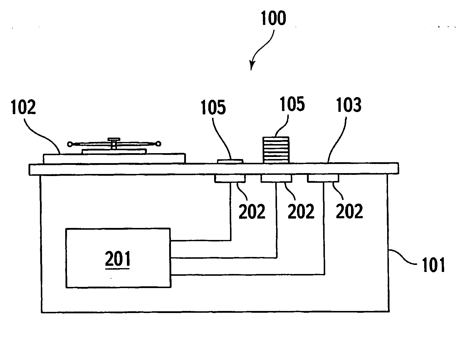
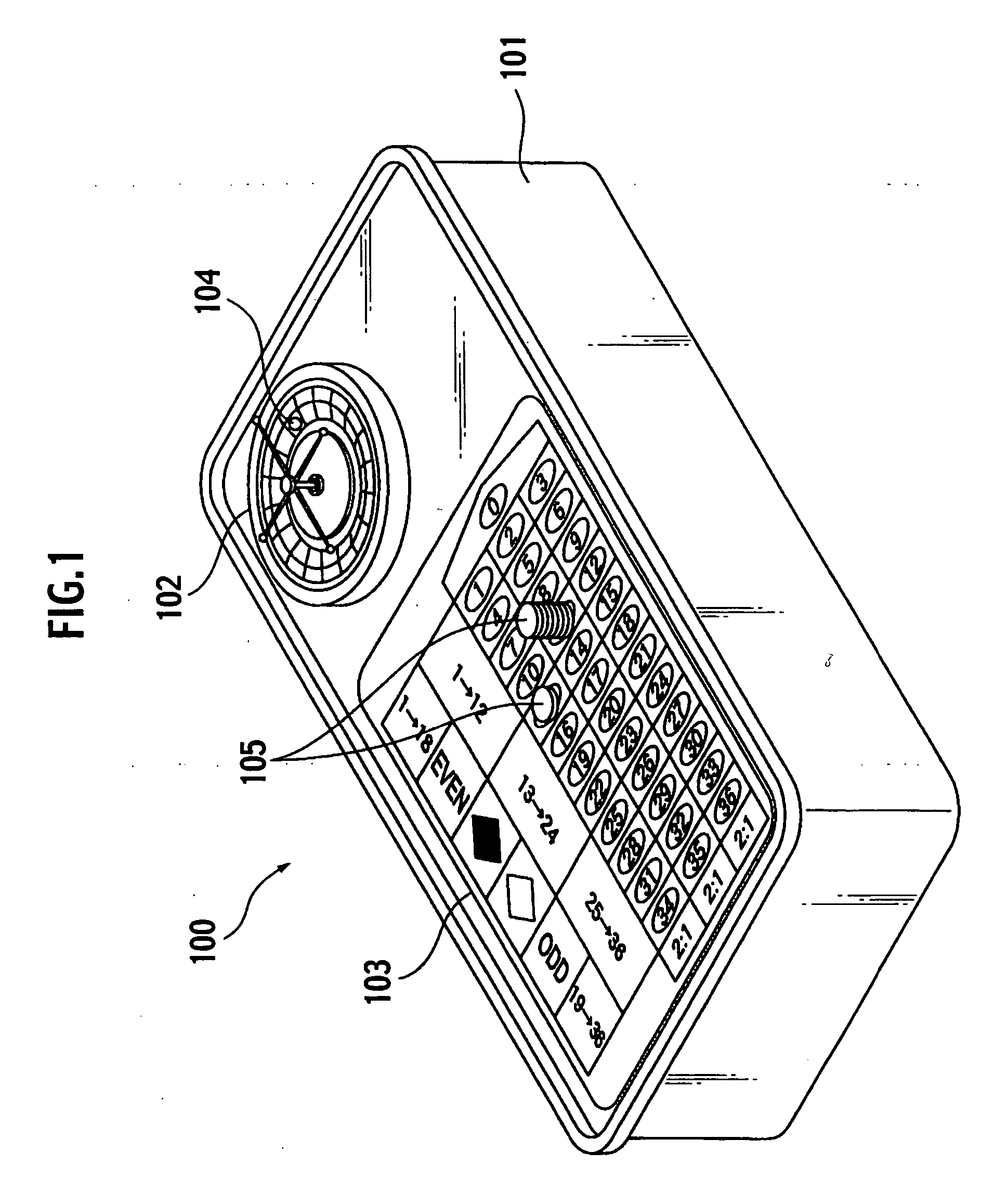
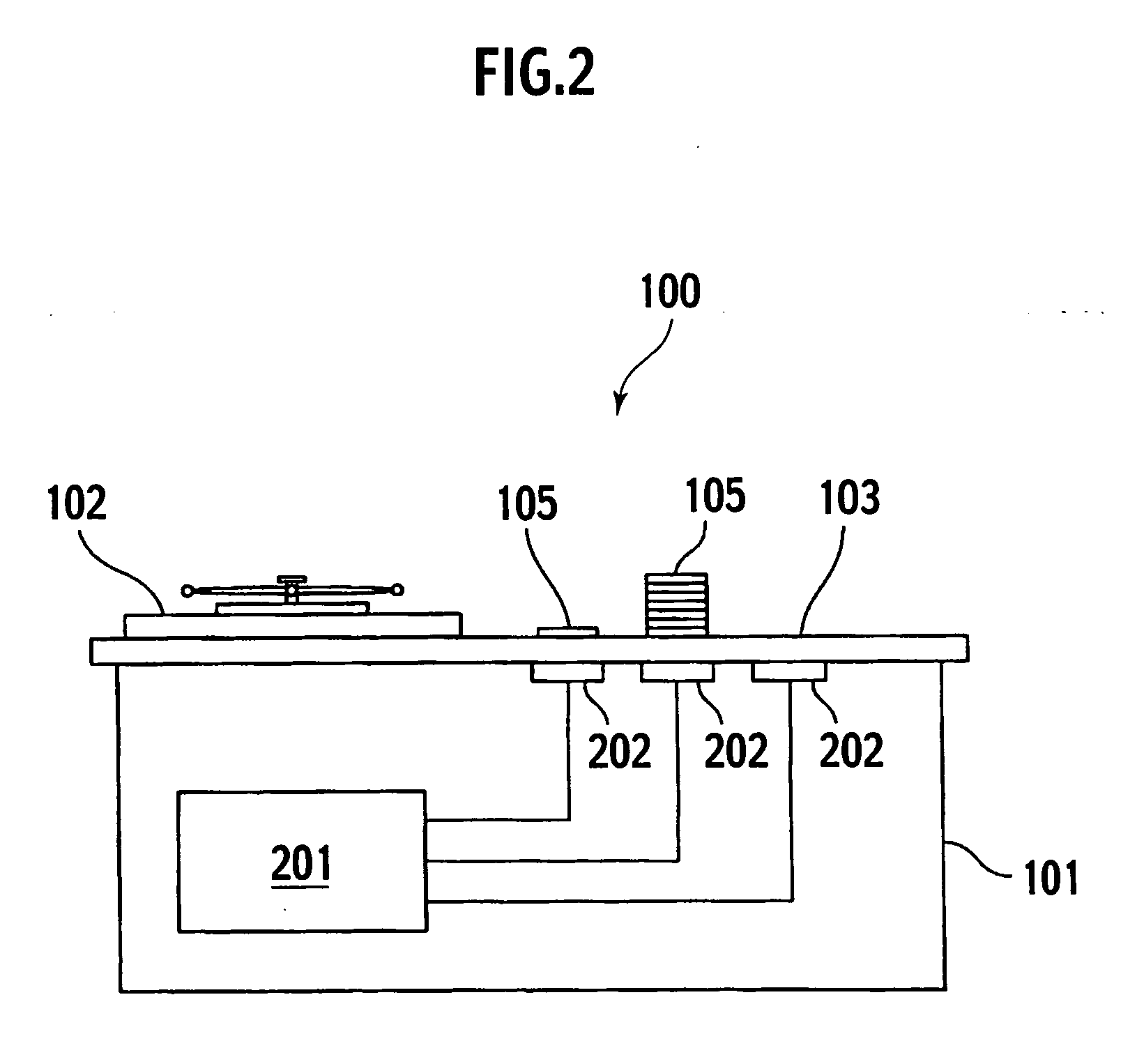
[0029] A gaming machine 100 is an apparatus which enables a player, to play a roulette game. As shown in FIGS. 1 and 2, the gaming machine 100 comprises a main body 101, a wheel 102, a layout 103, a ball 104, a plurality of game chips 105, a main control device 201 and a plurality of readers / writers 202.

[0030] The main body 101 is formed in to a table shape. The wheel 102 has pockets corresponding to numerals “0” to “36” colored red or black, and is disposed on an upper surface of the main body 101. The layout 103 has betting targets (betting areas) corresponding to numerals / colors of “1→18”, “19→36”, “1→12”, “13→24”, “25→36”, “0” to “36”, “red”, “black”, “odd number” and “even number”, and is disposed on the upper surface of the main body 101. The ball 104 is stored in the wheel 102. The game chip 105 is a tool which is employed to indicate ...


PUM


Abstract

A game chip transmits information in response to an inquiry from a reader / writer. The game chip comprises an IC device, an antenna coil unit, a first ring and a second ring. The IC device constitutes an electromagnetic induction coupling circuit with the reader / writer and stores information. The antenna coil unit is connected to the IC device and generates an induced current by a magnetic flux emitted from the reader / writer to supply power to the IC device when the inquiry is received. The first ring induces the magnetic flux emitted from the reader / writer in one of directions of moving away from and approaching the reader / writer. The second ring induces the magnetic flux induced by the first ring in the other of the directions of moving away from and approaching the reader / writer.

Description

CROSS REFERENCE TO RELATED APPLICATION [0001] This application claims benefit of priority under 35 U.S.C. §119 to Japanese Patent Application No. 2004-367241, filed on Dec. 20, 2004 and No. 2005-006076 filed on Jan. 13, 2005, the entire contents of which are incorporated by reference herein. BACKGROUND OF THE INVENTION [0002] 1. Field of the Invention [0003] The present invention relates to a game chip, and more specifically to a game chip capable of being recognized by a reading device such as a reader / writer. [0004] 2. Description of the Related Art [0005] There has conventionally been available a gaming machine that imitates a game in which a game table is employed and allows a player to make a bet without using real betting chips. The player inputs a betting target and the number of betting chips to the gaming machine by using buttons disposed on a control panel. However, the gaming machine has no function of permitting the player to directly put the betting chips on a game tabl...

Claims


Application Information

Patent Timeline
IPC IPC(8): A63F13/00
CPCA63F5/00A63F2003/00662G07F1/06
Inventor KOYAMA, TOSHIMINONAKA, NOBUYUKIMIGITA, JITUO
Owner MINERVA
Learn More