
Method and device for modifying software in a control unit and corresponding control unit

Inactive Publication Date: 2006-07-13
ROBERT BOSCH GMBH
View PDF12 Cites 6 Cited by
  • Summary
  • Abstract
  • Description
  • Claims
  • Application Information

AI Technical Summary

Benefits of technology

[0003] Therefore, it is an objective of the present invention to reduce this time requirement for flashing a control unit, which will result in additional advantages as well.
[0006] That is to say, to implement the changes of the existing software, that is, the old software parts, a patch manager, in particular a central patch manager, is installed, with the aid of which the parts of the software to be changed may be changed in a targeted manner by entry and exit. On the one hand, this advantageously allows for a marked reduction of the extensive time needed for flashing large software sections or software parts, since on the one hand, as already hinted at above, it is not the entire software that is newly written in and on the other hand also the time required for changing the software, that is, particularly to erase it and to write it in anew, is economized.
[0007] This additionally results in a higher flexibility in changing software and software parts and on the other hand in a reduced susceptibility to error by the fact that software parts are overwritten or erased and newly written-in as little as possible.

Problems solved by technology

In the automotive industry in particular, evermore complex functions are implemented in the individual control units with the aid of software.
Due to the existing size of the software, flashing a control unit, for example, now already takes up to 30 minutes.

Method used


Image

  • Method and device for modifying software in a control unit and corresponding control unit
  • Method and device for modifying software in a control unit and corresponding control unit
  • Method and device for modifying software in a control unit and corresponding control unit

Examples


Embodiment Construction

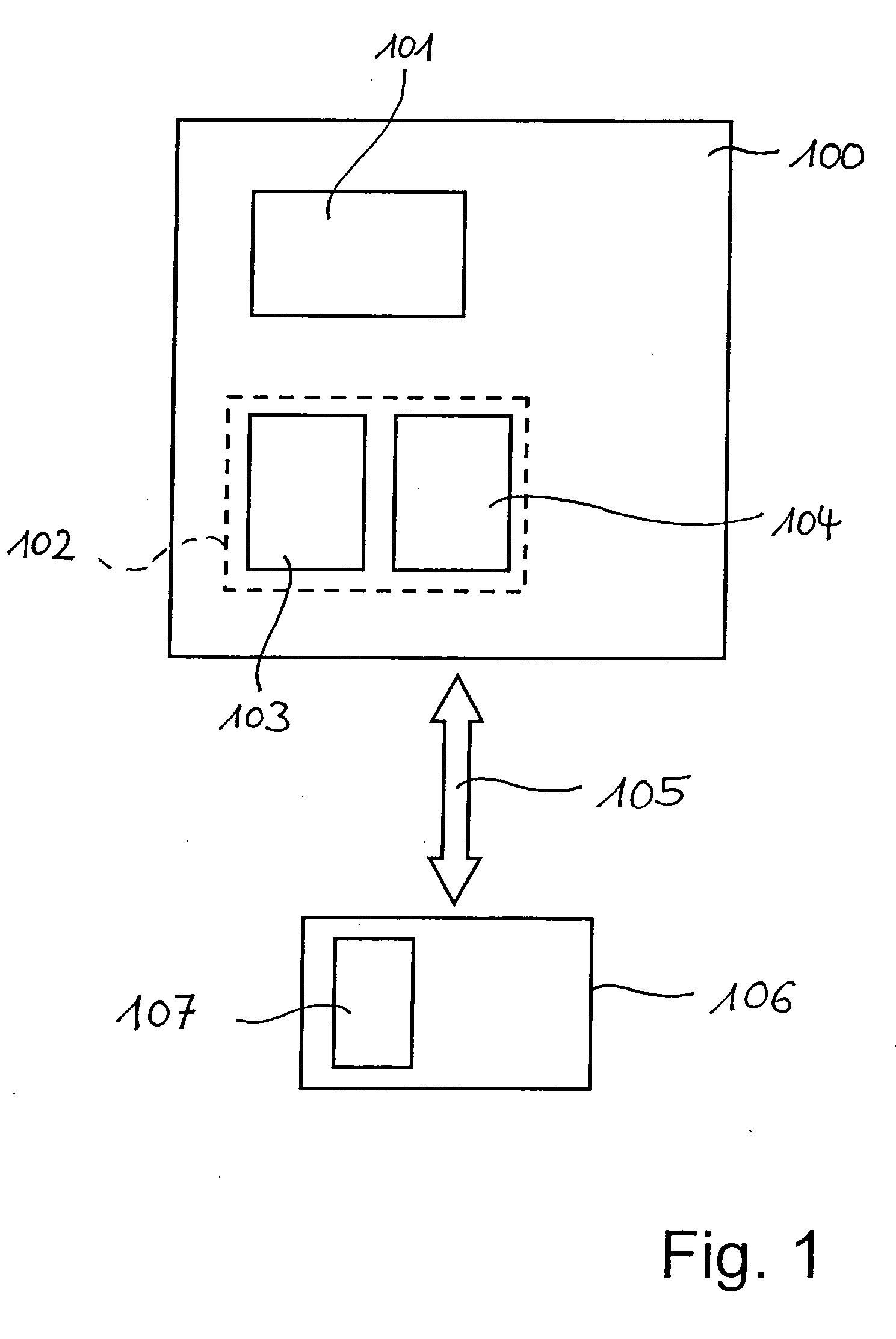
[0018]FIG. 1 shows a control unit 100 having a processing unit 101, particularly a microcontroller as well as memory arrangement 102, particularly divided into two memory areas 103 and 104. These memory areas 103 and 104 may exist in the same memory or in different memories of control unit 100. Via an interface 105, which may represent in addition to a wired also a wireless connection, the appropriate new software parts are introduced from a source 106, for example, another computer, by second memory arrangement 107 into control unit 100. Due to the fact that only the data to be changed are transmitted, that is, only the new software parts and not the entire software, which results in significantly lower transmission rates, it is possible to use in particular also air interfaces, that is, radio, ultrasound, infrared etc. In addition, however, wired transmission is also possible at this location.

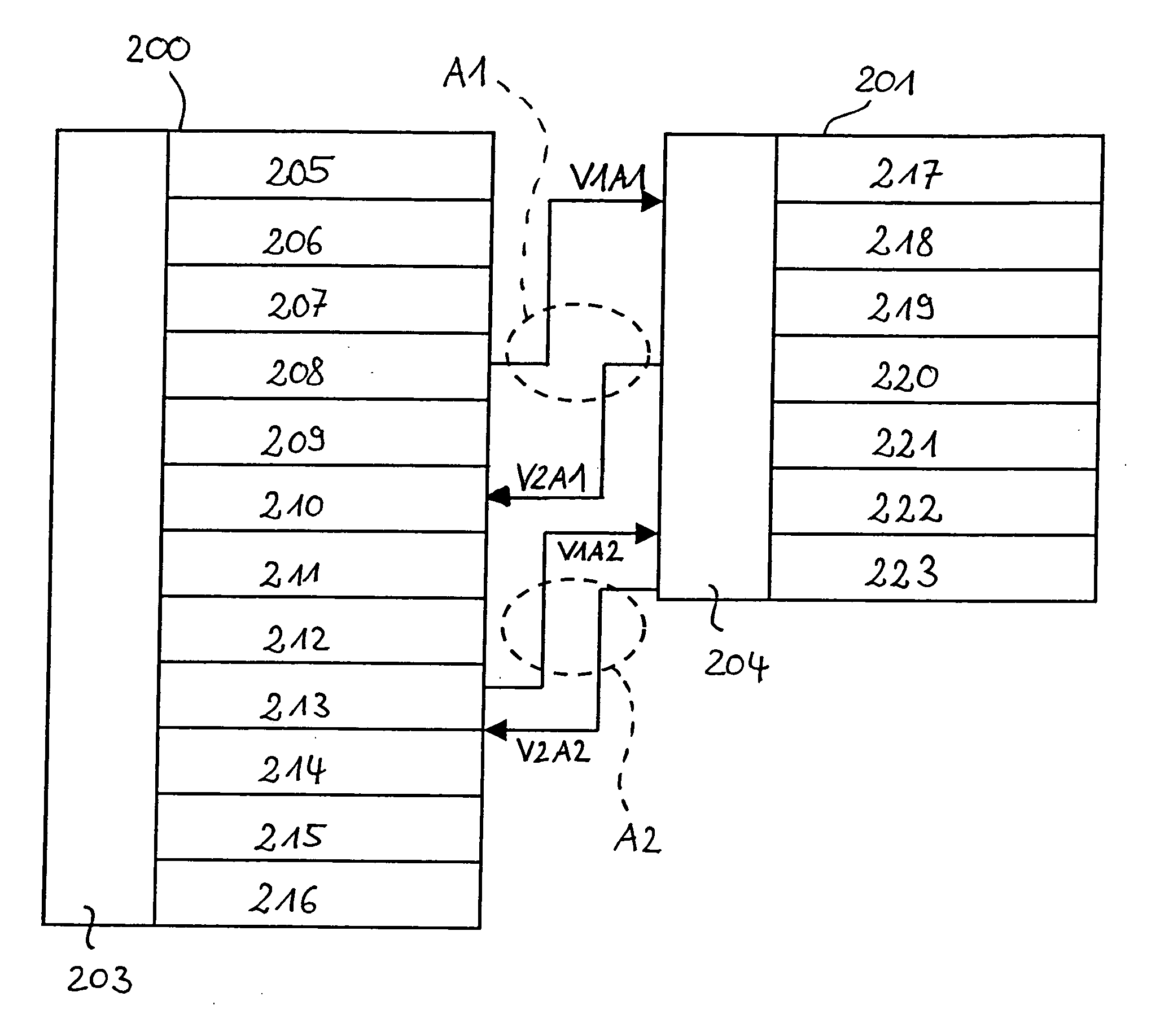
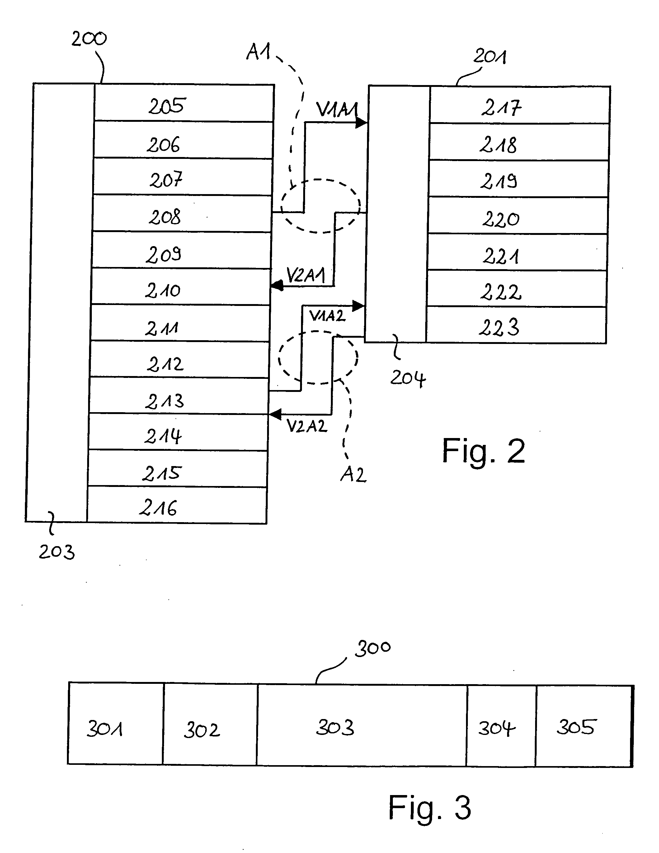
[0019]FIG. 2 now shows a first memory area 200 and a second memory area 201, in particul...


PUM


Abstract

A method and device for changing software in a first memory area in a control unit for controlling operational sequences, the execution of old software parts being replaced by the execution of new software parts and the old software parts being written into the first memory area, the new software parts being written into a second memory area and, due to a first branching in the first memory area, instead of the old software parts being executed in the first memory area, the new software parts are executed in the second memory area, the system, following the execution of the new software parts, branching back again into the first memory area via a second branching in the second memory area and the execution of the other software distinct from the old software parts being continued in the first memory area, the old software parts remaining in the first memory area.

Description

FIELD OF THE INVENTION [0001] The present invention relates to a method and a device for changing software in a first memory area in a control unit as well as a corresponding control unit and a computer program for implementing the method. BACKGROUND INFORMATION [0002] In the automotive industry in particular, evermore complex functions are implemented in the individual control units with the aid of software. More and more frequently it is necessary to incorporate changes of the software in the control unit just prior to or also following the delivery to end customers. The changes of the software of a control unit are generally handled in such a way that the changes are incorporated into a new software integration version and that this newly prepared software is loaded completely into the control unit, in particular by storing it in a so-called flash EPROM memory, i.e. by flashing. Due to the existing size of the software, flashing a control unit, for example, now already takes up t...

Claims


Application Information

Patent Timeline
IPC IPC(8): G06F9/44G06F9/445G11C16/10
CPCG06F8/665G11C16/102G06F8/654
Inventor JOEST, PETER
Owner ROBERT BOSCH GMBH
Learn More