Solar-powered temperature regulation system for the interior of an automobile/motor vehicle

Inactive Publication Date: 2006-07-20
KHALIL MAGED
View PDF2 Cites 11 Cited by
  • Summary
  • Abstract
  • Description
  • Claims
  • Application Information

AI Technical Summary

Benefits of technology

[0014] The temperature regulation system consists of photovoltaic cells, a power supply, and an open ended mechanical unit having sides for supporting a heat pump. The photovoltaic cells can be comprised of solar cells attached one to another for generating energy. The solar cells can be connected to the power supply which controls the distribution of energy and the interaction between the system and the vehicle. The power supply can also activate the heat pump, such as a Peltier element. On at least one side of the mechanical unit, openings can be provided to accommodate one or more Peltier elements, having an inner surface and an outer surface. Each

Problems solved by technology

Although thermoelectric(TE) modules used as thermoelectric generators are rather inefficient, they may be used as thermocouples for temperature measurements.
When power is applied to the element, the hot side will begin ejecting this as heat to the heat sink causing it to rise in temperature.
In TE applications, however, a heat sink alone is not able to remove a sufficient amount of heat by natural convection in order to keep the hot side at an acceptably low temperature.
It is very well-known that, when an automobile/motor vehicle is parked under the sun, the interior becomes very hot.
Moreover, some devices still use an environmental pollutant, namely a coolant.
However, under such circumstances, a solar powered heating system would not be very efficient because there would be very little solar energy available.
In U.S. Pat. No. 6,662,572, there were two criticisms of the approach undertaken in U.S. Pat. No. 4,955,203, namely,

Method used


Image

  • Solar-powered temperature regulation system for the interior of an automobile/motor vehicle
  • Solar-powered temperature regulation system for the interior of an automobile/motor vehicle
  • Solar-powered temperature regulation system for the interior of an automobile/motor vehicle

Examples


Example

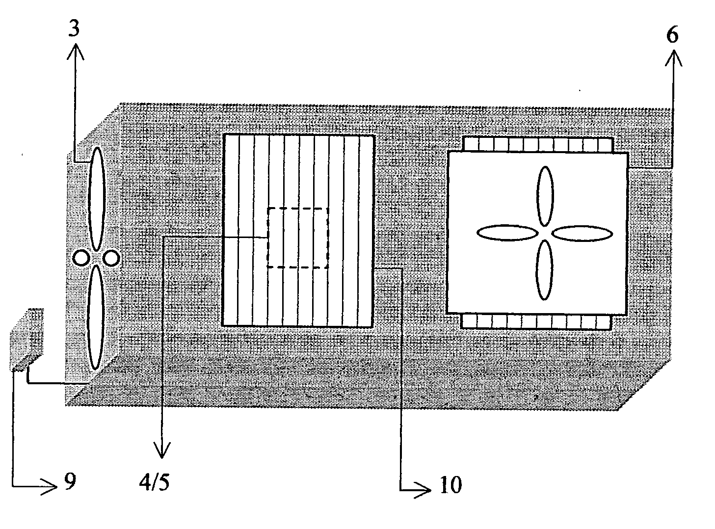
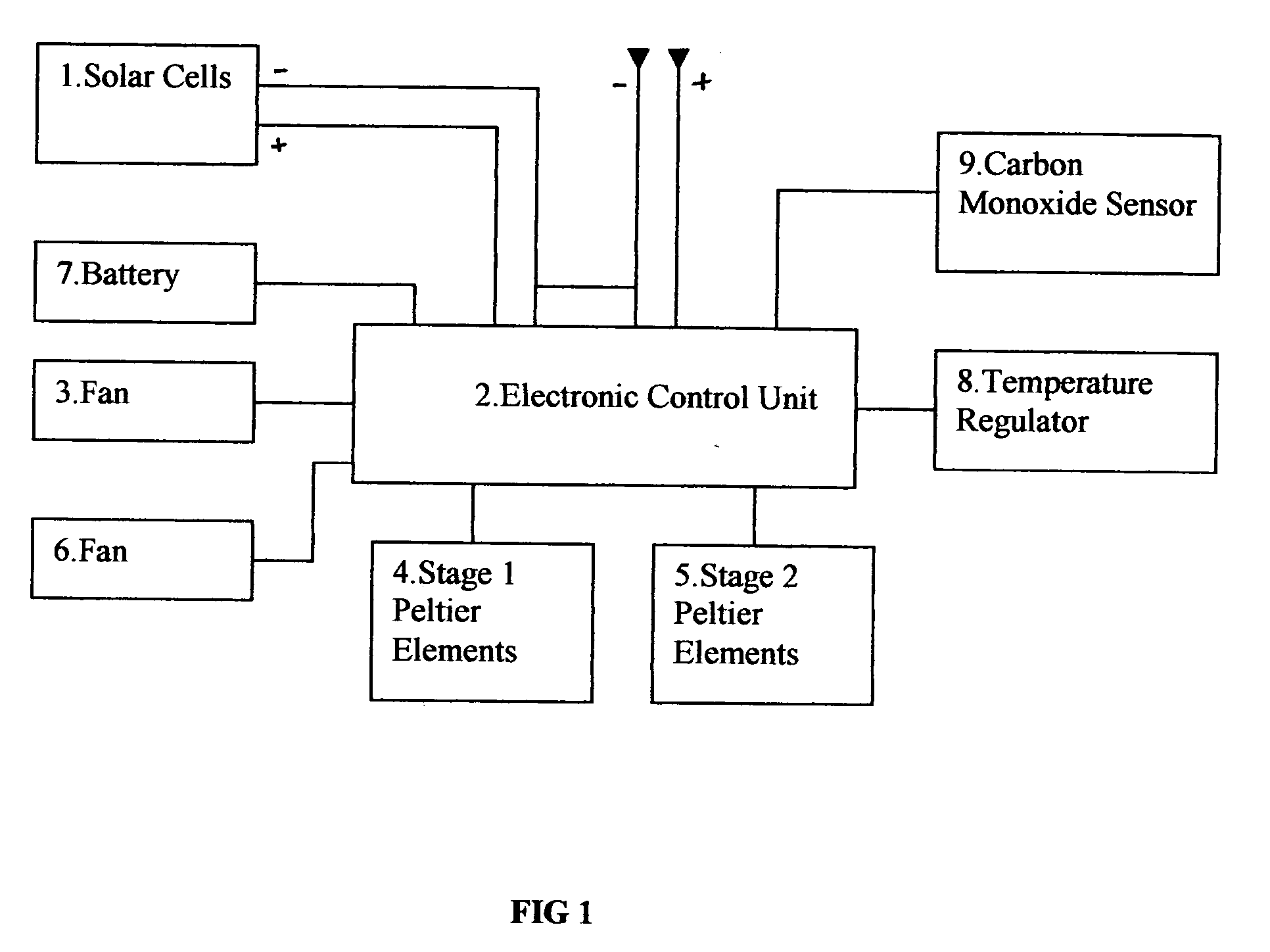
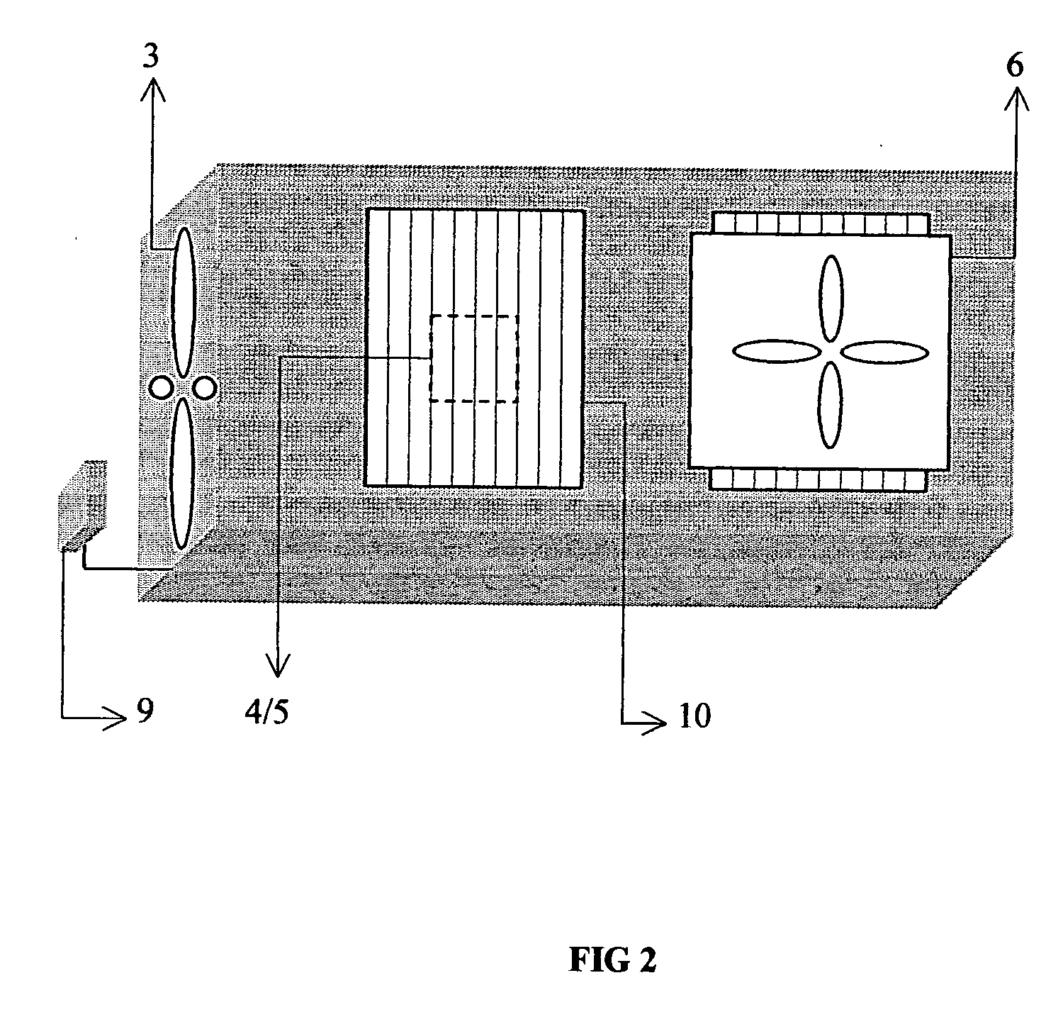
[0020] In FIG. 1, the temperature regulation system is illustrated as a block diagram. In this specific case, it is comprised of solar cells, 1, connected to an electronic control unit, 2, which distributes the electricity coming from the solar cells to the various parts of the mechanical unit, i.e. the two types of fans, 3&6, and the stage one Peltier elements, 4, when the automobile is parked. A certain number of Peltier elements (for example, 2) works very well to lower the temperature, substantially below the outside temperature, of the interior of an automobile when it is parked. By using a reasonable number of solar cells, the power coming from them is sufficient to activate approximately 50% to 60% of the elements' capacity. When the number of Peltier elements is increased (for example, 4) and the automobile is switched on, the interior temperature of the automobile is significantly reduced. The electronic control unit withdraws the extra needed electricity from the battery, ...


PUM


Abstract

A temperature regulation system, which can be used to cool the interior temperature of an automobile/motor vehicle, when it is parked under the sun, substantially below the external temperature, was designed and produced. The system was powered by solar cells, thus functioning without dissipating any energy from the vehicle's battery. The mechanical device of the system incorporated Peltier elements, heat sinks and fans, all controlled by a power supply in the form of a circuit board. When the automobile was switched on, the system could be further used as an automobile climate control unit, for heating or cooling, withdrawing the supplementary electricity from the battery, another feature controlled by the circuit board.

Description

CROSS-REFERENCE TO RELATED APPLICATIONS [0001]US Patent Documents4,280,330July 1981Harris et al.4,658,597April 1987Shum4,658,599April 1987Kajiwara4,955,203September 1990Sundhar5,205,781April 1993Kanno et al.5,233,227August 1993Kajimoto et al.5,588,909December 1996Ferng5,687,573November 1997Shih5,826,435October 1998Hange6,662,572December 2003HowardSTATEMENT REGARDING FEDERALLY SPONSORED RESEARCH OR DEVELOPMENT [0002] Not Applicable REFERENCE TO SQUENCE LISTING, A TABLE, OR A COMPUTER PROGRAM LISTING COMPACT DISC APPENDIX [0003] Not applicable FIELD OF THE INVENTION [0004] The invention relates to a temperature regulation system for the interior of an automobile / motor vehicle and, in particular, to a cooling system for the interior of a parked vehicle. BACKGROUND OF THE INVENTION [0005] Thermoelectric modules are solid-state devices (no moving parts) that convert electrical energy into a temperature gradient known as the “Peltier effect” or convert thermal energy from a temperature gr...

Claims


Application Information

Patent Timeline
IPC IPC(8): F25B21/02F25B27/00
CPCB60H1/00428Y02T10/88B60H1/00478
Inventor KHALIL, MAGED
Owner KHALIL MAGED
Why Eureka
Try Eureka