Test head positioning apparatus

a positioning apparatus and test head technology, applied in the direction of mechanical control devices, instruments, process and machine control, etc., can solve the problems of increasing the size and contributing significantly to the weight of the test head, and challenging the design of the apparatus

Inactive Publication Date: 2006-07-20
INTEST CORP
View PDF8 Cites 20 Cited by
  • Summary
  • Abstract
  • Description
  • Claims
  • Application Information

AI Technical Summary

Benefits of technology

[0017] In an exemplary embodiment of the present invention, a positioning apparatus for positioning a test head for testing electronic components is provided. The positioning apparatus includes an outer cylinder and a support coupled to the outer cylinder for supporting the test head. The positioning apparatus also includes a piston arranged within said outer cylinder such that the piston and the outer cylinder define a fluid compartment within the outer cylinder. The positioning apparatus also includes a pressure regulator for maintaining a pressure within the fluid compartment such that the test head may be suspended in a substantially weightless position, the substantially weightless position being adjustable in a vertical direction. The positioning apparatus also includes a lifting device for raising and lowering the outer cylinder. The lifting device includes a threaded drive mechanism coupled to the piston. The positioning apparatus also includes a drive apparatus for operating the threaded drive mechanism to move the test head to a predetermined position.
[0018] In another exemplary embodiment of the present invention, a positioning apparatus for positioning a test head for testing electronic components is again provided. The positioning apparatus includes a drive mechanism for moving the test head in a vertical direction. The positioning apparatus also includes a pneumatic compliant coupling mechanism coupled to said drive mechanism. The pneumatic compliant coupling mechanism supports the test head in a substantially weightless condition and provides a range of motion to the test head in the vertical direction. The pneumatic compliant coupling mechanism is positioned above and secured to the drive mechanism such that the drive mechanism moves the pneumatic compliant coupling mechanism when moving the test head in the vertical direction.
[0019] In another exemplary embodiment of the present invention, a method of positioning a test head for testing electronic components is provided. The method includes providing flow of a fluid into a fluid compartment coupled to the test head. The method also includes mechanically moving the test head to a desired position in a vertical direction using a drive mechanism. The method also includes fluidly suspending the test head in a substantially weightless condition by maintaining a fluid pressure in the fluid compartment positioned between the test head and the drive mechanism.

Problems solved by technology

In very sophisticated test heads, the circuitry may require that coolant be pumped through the test head, which contributes significantly to the test head's weight, as well as the weight and resiliency of the cable.
As semiconductor chips have and continue to become faster and more complex, the size and weight of test heads have continually grown larger.
Overall it is very challenging to design an apparatus that can freely move loads approaching many hundreds of kilograms with the precision needed to mate hundreds or thousands of individual delicate electrical contacts.
Also, during testing the handling apparatus may generate mechanical vibrations whose energy must be absorbed by the system.
In a telescoping pneumatic system such as described in the '815 patent (see above) this could conceivably be achieved by controlling the air pressure in the cylinder as in an automobile lift; however, it could be difficult to adequately control.
Further, as test heads have become larger and more massive their positioning systems have correspondingly become larger and taller, particularly as vertical stroke requirements have increased.
Also as test heads have become more and more massive, it has become less and less desirable to use counterweights, which must be somewhat greater than the combined mass of the test head, its support structure, and the cable it supports.
An all-pneumatic system, such as described in the '815 patent, is limited in stroke; and, as previously mentioned, accurate positioning is difficult to achieve.
Thus, the vertical compliance mechanism requires valuable space beneath the column, which could limit the vertical reach and / or be limited in overall compliant range.
This technology has not been applied to test head positioning systems, and it does not appear to offer compliance.

Method used


Image

  • Test head positioning apparatus
  • Test head positioning apparatus
  • Test head positioning apparatus

Examples


Embodiment Construction

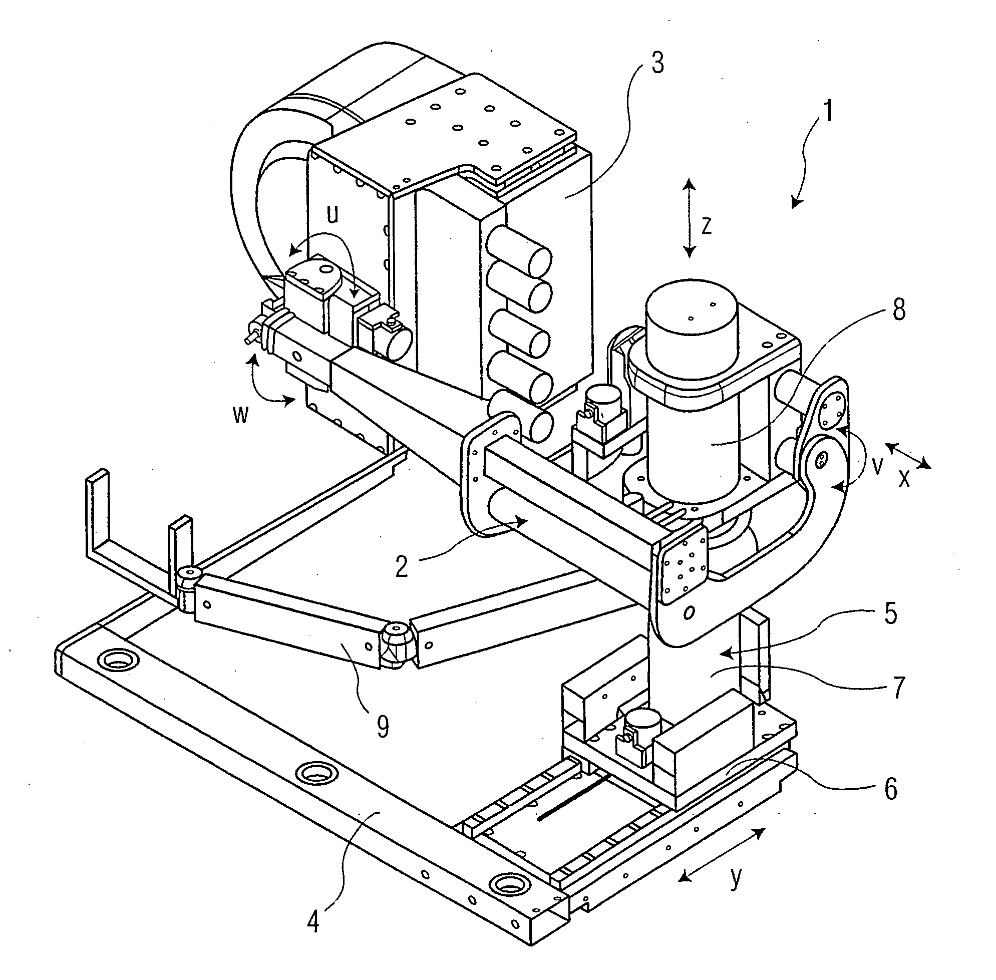
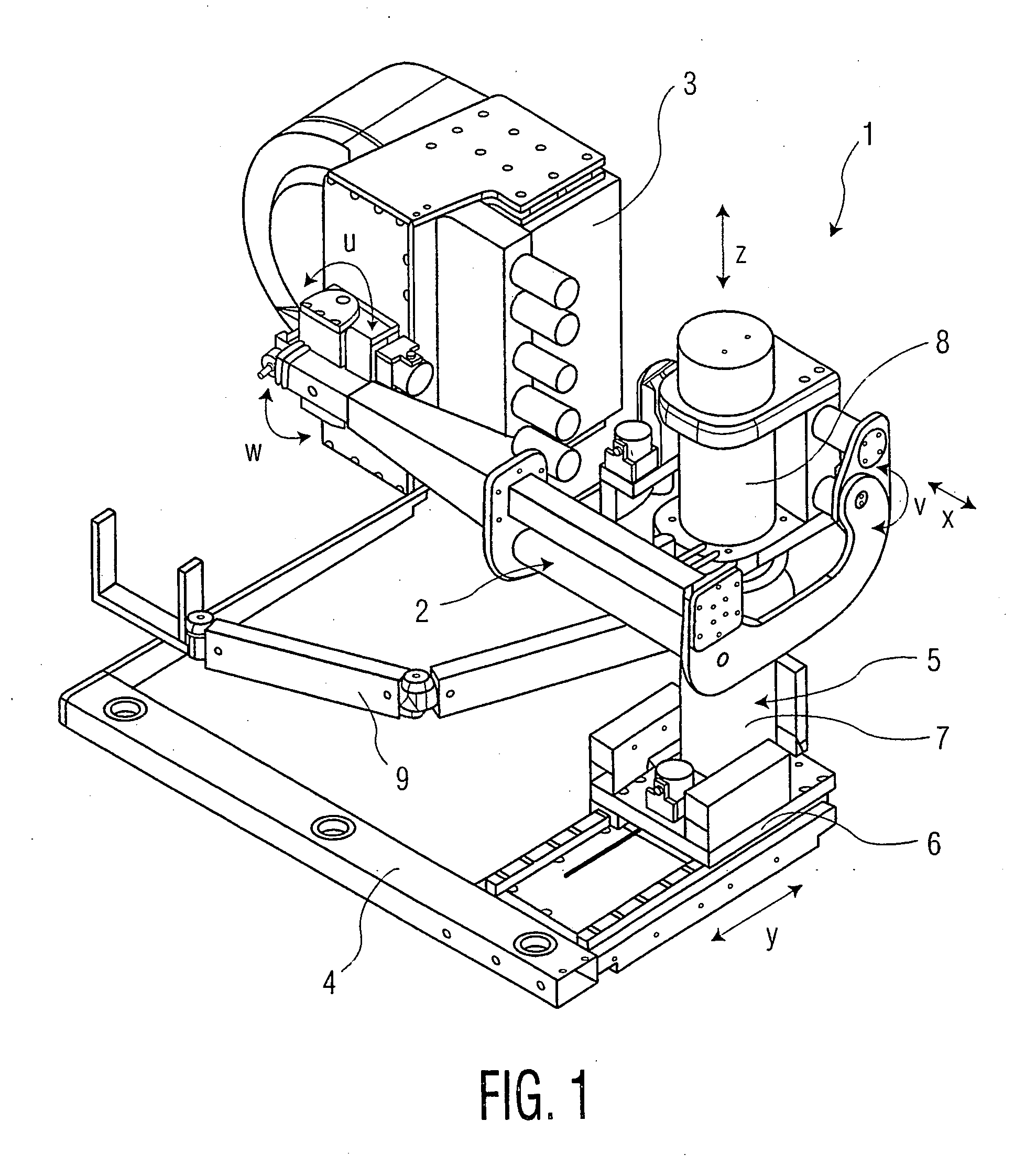
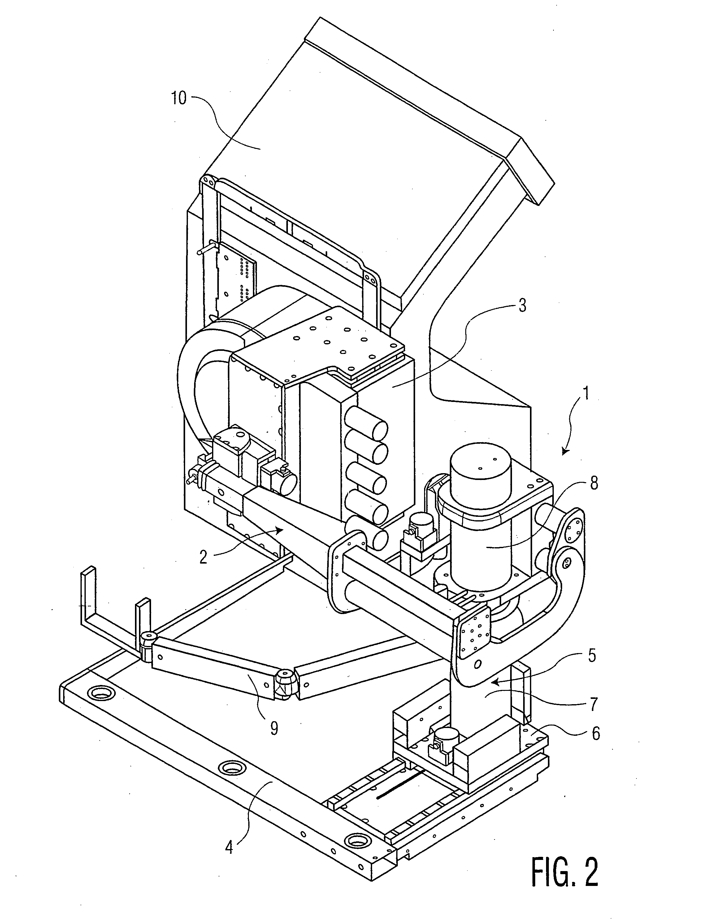
[0030]FIGS. 1 and 2 provide perspective views of a positioning apparatus 1 including a carrier-arm device 2 for supporting a test head 3 for testing electronic components.

[0031] Positioning apparatus 1 includes base frame 4 resting on the floor from which a vertical column arrangement 5 extends upward. Column arrangement 5 can be moved in the y-direction via a carriage 6. Carrier-arm device 2 can be moved in relation to column arrangement 5 in the x-direction. Column arrangement 5 includes a bottom tubular inner cylinder 7 and a top tubular outer cylinder 8 that is placed on inner cylinder 7 such that cylinders 7 and 8 are telescopically engaged with one another. By adjusting the height of outer cylinder 8 in relation to inner cylinder 7, carrier-arm device 2, which is attached to outer cylinder 8 (and test head 3) can be adjusted in height, i.e., in the z-direction. Moreover, carrier-arm device 2 may swivel about a horizontal axis in the v-direction. Test head 3 may swivel about a...


PUM


Abstract

A positioning apparatus for positioning a test head for testing electronic components is provided. The positioning apparatus includes an outer cylinder and a support coupled to the outer cylinder for supporting the test head. The positioning apparatus also includes a piston arranged within said outer cylinder such that the piston and the outer cylinder define a fluid compartment within the outer cylinder. The positioning apparatus also includes a pressure regulator for maintaining a pressure within the fluid compartment such that the test head may be suspended in a substantially weightless position, the substantially weightless position being adjustable in a vertical direction. The positioning apparatus also includes a lifting device for raising and lowering the outer cylinder. The lifting device includes a threaded drive mechanism coupled to the piston. The positioning apparatus also includes a drive apparatus for operating the threaded drive mechanism to move the test head to a predetermined position.

Description

FIELD OF THE INVENTION [0001] The present invention relates, in general, to positioning systems for test heads for testing electronic components, and more specifically, to positioning systems for providing vertical compliant motion of test heads for testing electronic components. BACKGROUND OF THE INVENTION [0002] In the automatic testing of electronic components such is integrated circuits (IC's), it is customary to use a system that includes a “handling apparatus” to handle the item to be tested. The handling apparatus may be a packaged device handler, a wafer prober or other handling equipment; the type of handling apparatus used may depend upon the stage of manufacturing or development where the testing occurs. The handling apparatus brings each device under test (DUT) in turn to an included test site where it is connected to a test socket, probe card, or the like, where it may be electronically tested. [0003] The electronic testing itself is provided by a large and elaborate au...

Claims


Application Information

Patent Timeline
Patent Type & Authority Applications(United States)
IPC IPC(8): B25J18/00B23Q1/26B23Q11/00B25J18/02B25J19/00G01R1/073G01R31/28
CPCB23Q1/26B23Q11/001B25J18/025Y10T74/20305B25J19/002G01R31/2887B25J19/0012
Inventor MUELLER, CHRISTIAN
Owner INTEST CORP
Why Eureka
Try Eureka