Micro heat pipe with poligonal cross-section manufactured via extrusion or drawing

a micro-heat pipe and cross-section technology, which is applied in the direction of indirect heat exchangers, lighting and heating apparatus, tubular elements, etc., can solve the problems of reducing the heat dissipation rate, and generating a larger amount of heat per unit area, etc., to achieve simple structural modification, induce strong capillary force, and manufacture easily via simple drawing or extrusion

Inactive Publication Date: 2006-07-20
MOON SEOK HWAN +6
View PDF18 Cites 13 Cited by
  • Summary
  • Abstract
  • Description
  • Claims
  • Application Information

AI Technical Summary

Benefits of technology

[0014] As described above, a micro heat pipe according to the present invention can be manufactured easily via simple drawing or extrusion. The micro heat pipe according to the present invention can induce strong capillary force through simple structural modifications, without need to install a separate wick for flowing working fluid.

Problems solved by technology

However, such chips and systems generate a larger amount of heat per unit area, so that effective cooling techniques are required.
However, as the size of heat sinks is reduced more and more, the heat dissipating area becomes smaller and the heat dissipating rate becomes lower.
Meanwhile, fans have a limitation in that their size cannot be reduced unlimitedly.
In addition, the fans are less reliable than other cooling devices.
However, when such a heat pipe is compressed, a wick thereof undergoes structural changes, and the heat transferring performance is greatly deteriorated.

Method used


Image

  • Micro heat pipe with poligonal cross-section manufactured via extrusion or drawing
  • Micro heat pipe with poligonal cross-section manufactured via extrusion or drawing
  • Micro heat pipe with poligonal cross-section manufactured via extrusion or drawing

Examples


Embodiment Construction

[0021] The present invention will be described more fully with reference to the accompanying drawings, in which exemplary embodiments of the invention are shown. This invention may, however, be embodied in many different forms and should not be construed as being limited to the embodiments set forth herein; rather, these embodiments are provide so that this disclosure will be thorough and complete, and will fully convey the concept of the invention to those skilled in the art.

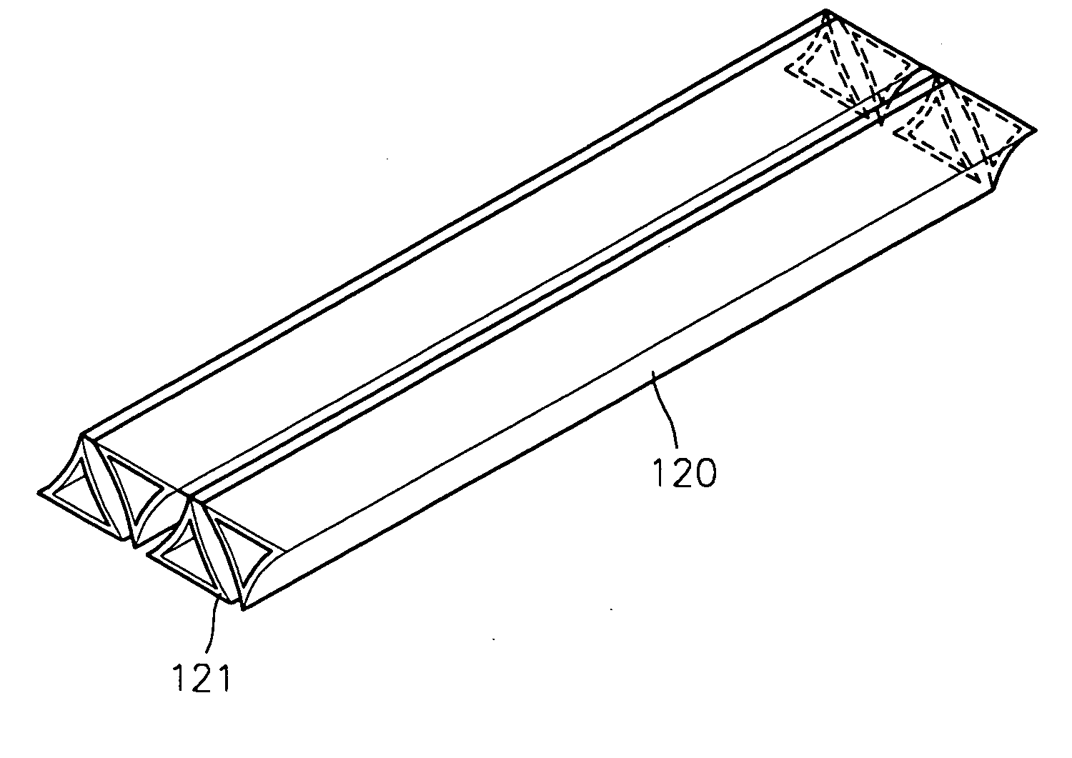
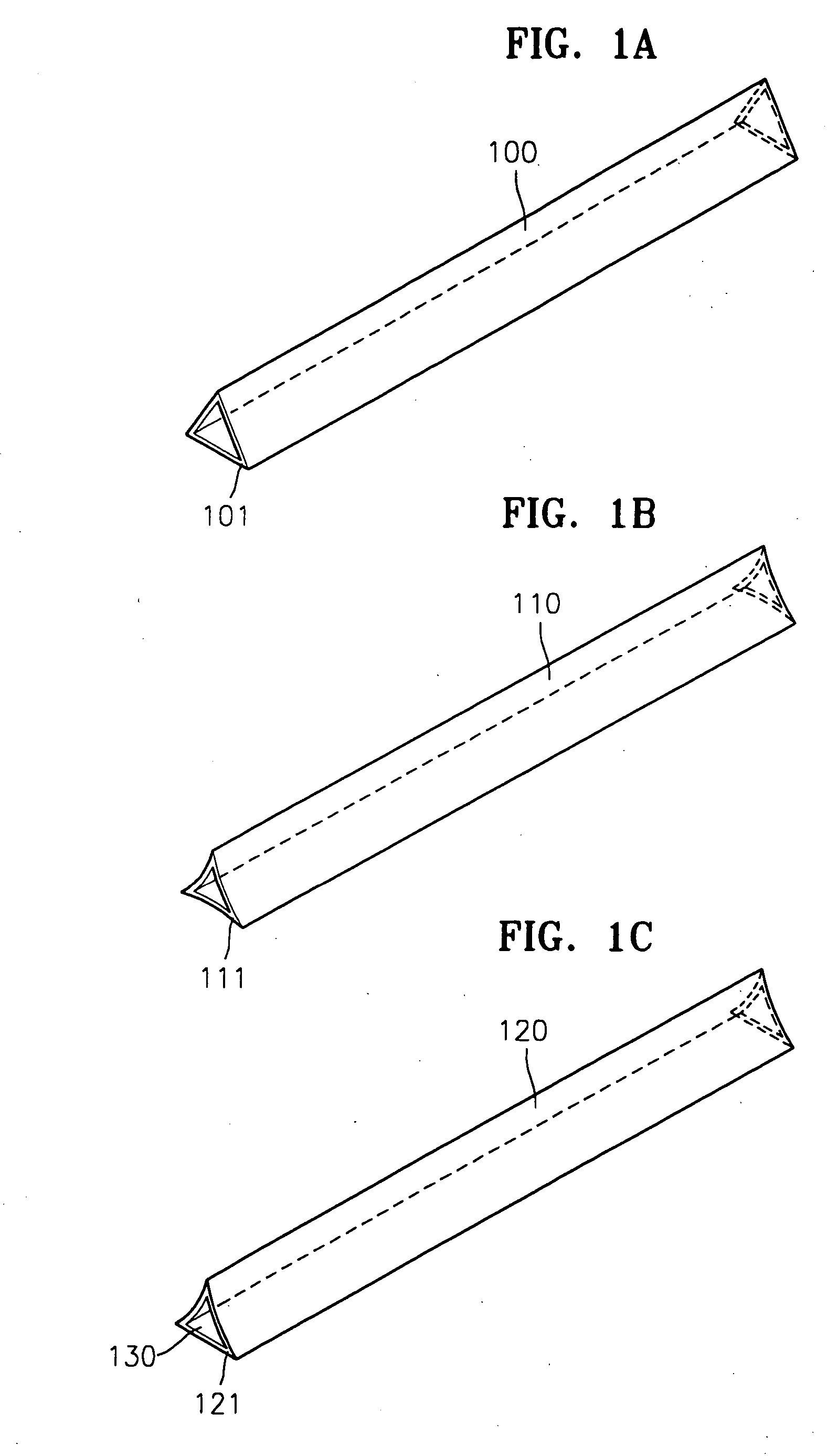
[0022] Referring to FIGS. 1A through 1C, which are perspective views of micro heat pipes having a triangular cross-section according to an embodiment of the present invention, the micro heat pipes are manufactured via drawing. Working fluid is allowed to flow by capillary force generated at the edges 101, 111, and 121 of the micro heat pipes and a wick acting as a return path of the working fluid from a condenser section toward an evaporator section is not required. In other words, in the micro heat pipes with...


PUM


Abstract

A method for fabricating a metal micro heat pipe with a polygonal cross-section including at least two concave sides to allow working fluid to flow by capillary force generated at the edges of the micro heat pipe. The concave sides are each formed of a single metal layer via a single drawing process. The polygonal cross-section is triangular, and the micro heat pipe is formed of a single metal plate.

Description

[0001] The application is a Continuation of U.S. patent application Ser. No. 10,654,686 filed on Sep. 3, 2003 which claims the priority of Korean Patent Application No. 2002-80869, filed on Dec. 17, 2002, in the Korean Intellectual Property Office.BACKGROUND [0002] 1. Field of the Invention [0003] The present invention relates to a heat pipe, and more particularly, to a micro heat pipe for small, thin-film type electronic devices. [0004] 2. Description of the Related Art [0005] With the advances of semiconductor manufacturing related technologies, chips packaged in electronic devices and systems have become smaller and have become more highly integrated. However, such chips and systems generate a larger amount of heat per unit area, so that effective cooling techniques are required. Specially, the latest small, thin-film type electronic devices require much smaller cooling devices. [0006] Conventionally, heat sinks, fans, small circular heat pipes having a diameter of 3 mm or greate...

Claims


Application Information

Patent Timeline
Patent Type & Authority Applications(United States)
IPC IPC(8): F28D15/02F28F1/02F28F1/04
CPCF28D15/0233F28D2015/0225F28F1/022F28F1/045
Inventor MOON, SEOK HWANYUN, HO GYEONGKO, SANG CHOONHWANG, GUNNCHOY, TAE GOOJUN, CHI HOONKIM, YOUN TAE
Owner MOON SEOK HWAN
Why Eureka
Try Eureka