Fuel injector reducing stress concentration

a fuel injector and stress concentration technology, applied in the field of fuel injectors, can solve problems such as durability degradation or breakage of the nozzle body, and achieve the effect of inhibiting excessive stress

Inactive Publication Date: 2006-07-20
DENSO CORP
View PDF7 Cites 6 Cited by
  • Summary
  • Abstract
  • Description
  • Claims
  • Application Information

AI Technical Summary

Benefits of technology

[0019] Thus, stress concentration in the connection cross portion between the high-pressure fuel passage and the bag-shaped hole portion can be alleviated even under high tensile stress since the cross angle is obtuse. As a result, excessive stress can be inhibited.

Problems solved by technology

As a result, problems such as a breakage or durability deterioration of a nozzle body due to excessive stress occur at a cross connection between a high-pressure fuel passage and a bag-shaped hole portion of a nozzle body.

Method used


Image

  • Fuel injector reducing stress concentration
  • Fuel injector reducing stress concentration
  • Fuel injector reducing stress concentration

Examples


Embodiment Construction

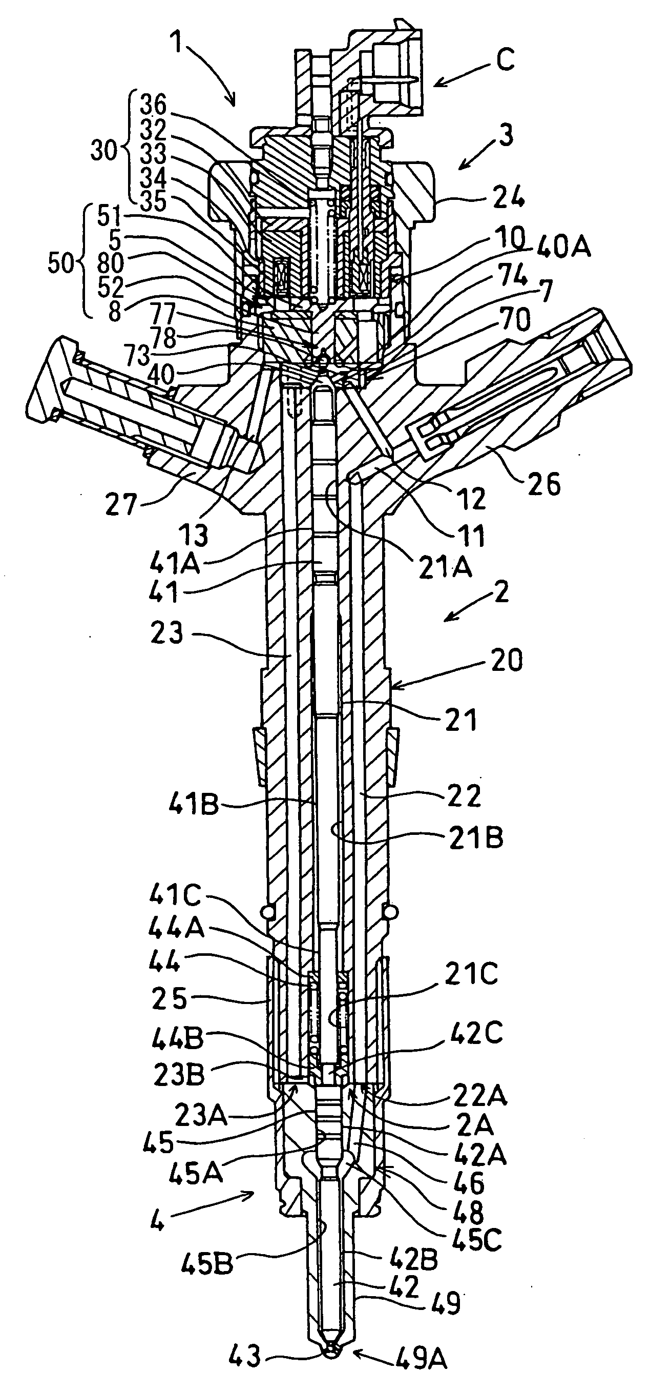
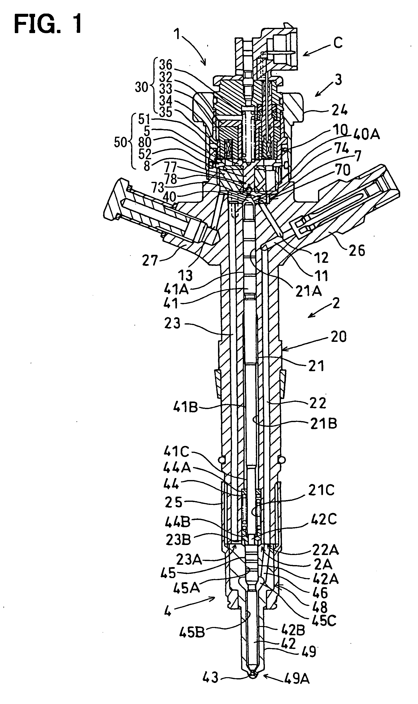
[0033] Referring to FIG. 1, an electromagnetically controlled type fuel injector (such as piezo type fuel injector) 1 that intermittently injects fuel into a combustion chamber of an engine is illustrated. The fuel injector 1 is used in an accumulator type (common rail type) fuel injection apparatus for a diesel engine and injects high-pressure fuel supplied from the common rail (not shown) into the combustion chamber of the engine. The injector 1 has an injector body 2, an electromagnetic valve 3 mounted to an upper end side of the injector body 2 and a fuel injection nozzle 4 fixed to a lower end side of the injector body 2.

[0034] The electromagnetic valve 3 has a connector C connected to a wiring harness extending from an engine control unit (ECU) (not shown). The electromagnetic valve 3 is controlled by a control signal output from the ECU.

[0035] The injector body 2 has a valve body 20 formed in a bar shape. The valve body 20 is formed with a cylinder 21 penetrating through an...


PUM


Abstract

On an inner wall of a bag-shaped hole portion of a nozzle body, a cross angle between the bag-shaped hole portion and a needle hole or an oblique high-pressure fuel passage of the nozzle body is made obtuse, i.e. at 90 degrees or larger, through an electrochemical machining process with a suitably-shaped electrode or through after-processing with a boring tool having a predetermined shape. The center of the bag-shaped hole portion may be deviated toward the high-pressure fuel passage or the high-pressure fuel passage may be connected to a maximum diameter portion of the bag-shaped hole portion to provide the obtuse cross angle. Thus, excessive stress on the inner wall of the bag-shaped hole portion or a breakage of the nozzle body due to a crack can be inhibited.

Description

CROSS REFERENCE TO RELATED APPLICATION [0001] This application is based on and incorporates herein by reference Japanese Patent Application No. 2005-7695 filed on Jan. 14, 2005. BACKGROUND OF THE INVENTION [0002] 1. Field of the Invention [0003] The present invention relates to a fuel injector injecting high-pressure fuel, which is pressurized by a high-pressure supply pump and stored under pressure in a common rail, into a combustion chamber of an internal combustion engine. [0004] 2. Description of Related Art [0005] A fuel injector is used in an accumulator fuel injection apparatus of a diesel engine or the like and injects high-pressure fuel supplied from a common rail into a combustion chamber of the engine. The fuel injector has an injector body equipped with an injection nozzle located on a front end side thereof, a drive device such as an electromagnetic valve located on a rear end side of the injector body and the like. The drive device receives a control signal from an eng...

Claims


Application Information

Patent Timeline
Patent Type & Authority Applications(United States)
IPC IPC(8): F02M41/16
CPCF02M47/027F02M55/008F02M61/12F02M61/168F02M2200/03F02M2200/8069
Inventor TOJO, SENTASHOGAKI, YOSHIROINABA, MANABU
Owner DENSO CORP
Why Eureka
Try Eureka