Plastic molding die
- Summary
- Abstract
- Description
- Claims
- Application Information
AI Technical Summary
Benefits of technology
Problems solved by technology
Method used
Image
Examples
Embodiment Construction
[0038] Next, an embodiment of the present invention will be explained in detail by referring to figures.
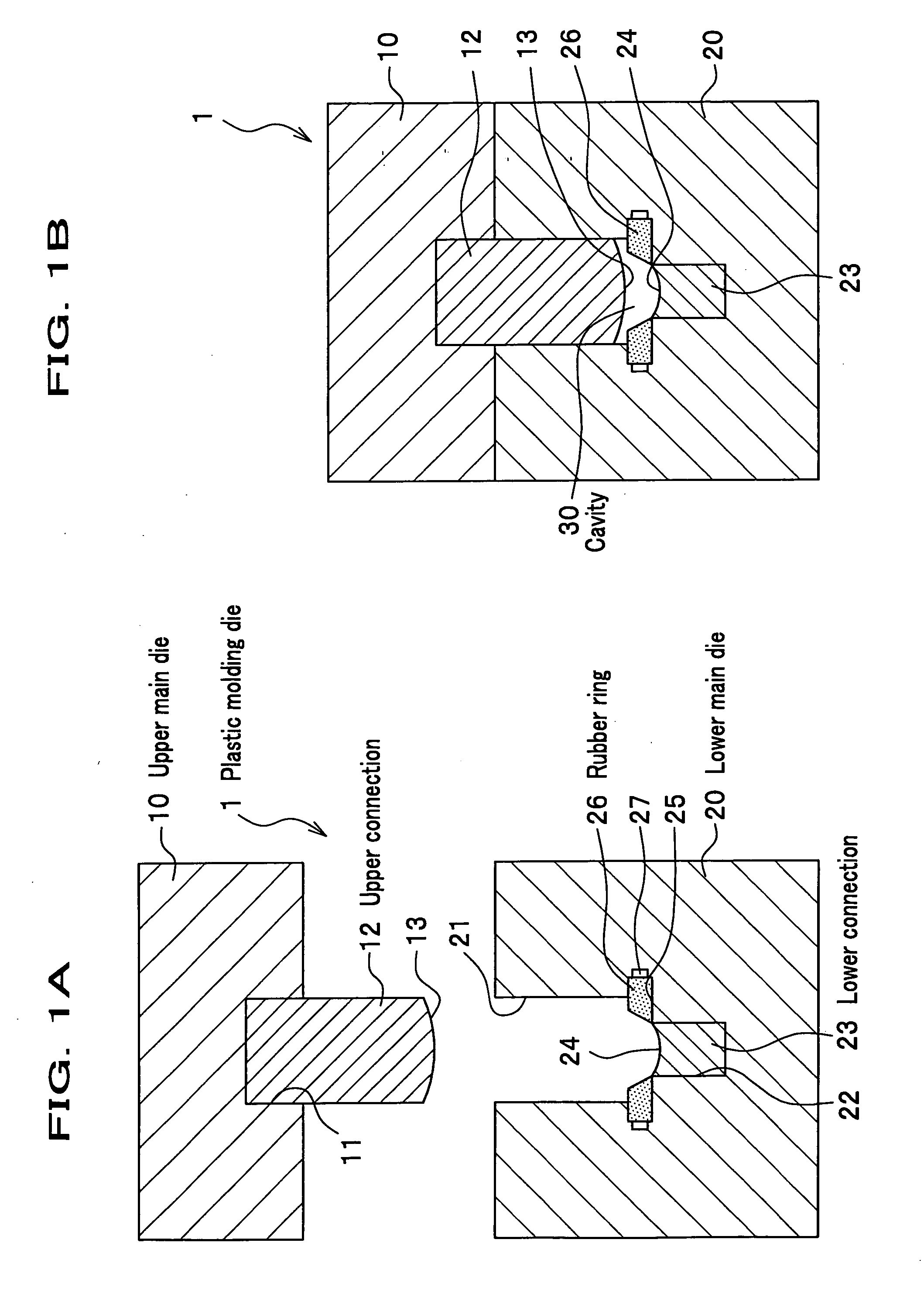
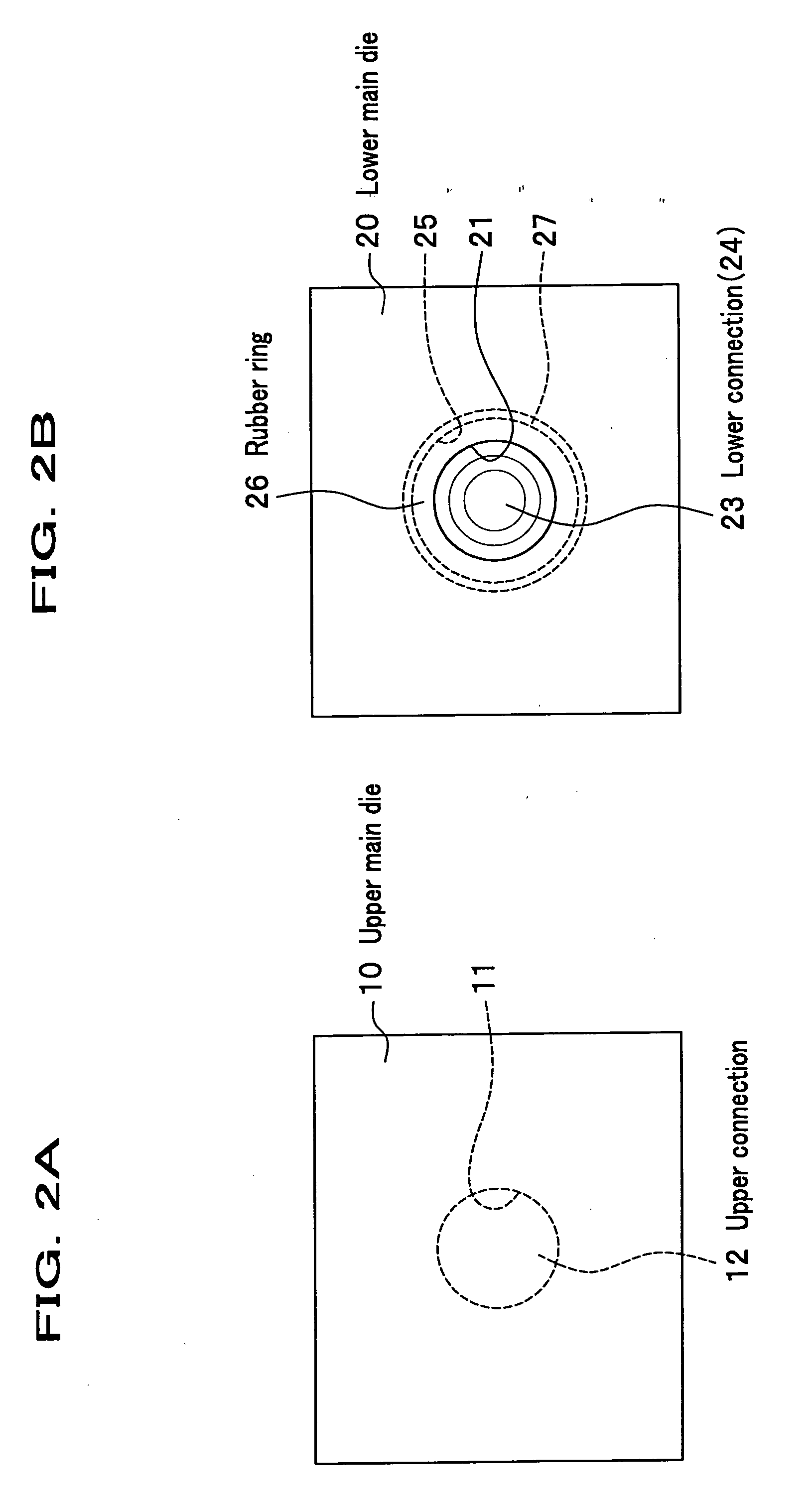
[0039]FIGS. 1A and 1B are views showing a plastic molding die according to an embodiment of the present invention. FIG. 1A is a side cross sectional view showing each main die being separated to each other, of a plastic molding die according to the embodiment. FIG. 1B is a side cross sectional view showing each main die being engaged with each other, of the plastic molding die according to the embodiment. FIGS. 2A and 2B are views showing the plastic molding die according to the embodiment. FIG. 2A is a plane view showing an upper main die of the plastic molding die according to the embodiment. FIG. 2B is a plane view showing a lower main die of the plastic molding die according to the embodiment.
[0040] In the embodiment, an example for manufacturing a plastic lens with compression molding of a plastic material will be used for explaining the present invention.
(Configuration o...
PUM
| Property | Measurement | Unit |
|---|---|---|
| Electrical resistance | aaaaa | aaaaa |
| Moldable | aaaaa | aaaaa |
| Elasticity | aaaaa | aaaaa |
Abstract
Description
Claims
Application Information
 - R&D
- Intellectual Property
- Life Sciences
- Materials
- Tech Scout
- Unparalleled Data Quality
- Higher Quality Content
- 60% Fewer Hallucinations
Browse by: Latest US Patents, China's latest patents, Technical Efficacy Thesaurus, Application Domain, Technology Topic, Popular Technical Reports.
© 2025 PatSnap. All rights reserved.Legal|Privacy policy|Modern Slavery Act Transparency Statement|Sitemap|About US| Contact US: help@patsnap.com


