Plasma display panel thermal dissipation-equilibration apparatus and mehtod

a technology of plasma display panel and thermal dissipation equilibrium, which is applied in the direction of casing/cabinet/drawer details, discharge tube main electrodes, incadescent cooling arrangements, etc. it can solve the problems of reducing the operational life of pdp panels, reducing the operational temperature of ic, and reducing the thermal imbalance. , the effect of preventing the reduction of the operational life of the pdp panel

Inactive Publication Date: 2006-07-20
AU OPTRONICS CORP
View PDF15 Cites 3 Cited by
  • Summary
  • Abstract
  • Description
  • Claims
  • Application Information

AI Technical Summary

Benefits of technology

[0016] It is another feature of an embodiment of the present invention to utilize the heat generated by the ICs to achieve a thermally equilibrated state for the entire PDP, thus preventing the reduction in PDP panel operational life. This feature may be achieved by the thermal pad and / or chassis structure being disposed in the non-display portion of the plasma display panel. Thus, the present invention reduces the thermal imbalance between the display portion and the non-display portion in the PDP panel.
[0017] As can be indicated from above, another feature of an embodiment of the present invention is to reduce the operational temperature of the IC without increasing cost or dimensional thickness.

Problems solved by technology

The same is true with flat-panel display modules, such as liquid crystal display (“LCD”) and PDP technologies, which generate enormous heat quantities.
Heat sinks have been utilized to quickly but relatively inefficiently dissipate the heat generated in integrated circuits (“IC”).
However, methods associated with heat sinks have several disadvantages.
Heat sinks in flat-panel devices increase device costs, weight and dimensional thickness.
All of these characteristics inevitably limit the application of heat sink configurations.
Various ICs can operationally endure temperatures as high as 70-85° C. However, high temperatures can adversely impact display performance characteristics of a flat-panel display.
Heat generated by the IC 101 is dissipated by the conventional heat sink 102 by means of conduction and convection, which is relatively inefficient.
This temperature differential can produce thermal stresses, hot spots, and thermal fatigue, ultimately reducing the operational life or performance characteristics of the PDP.
One of the most significant threats to the operational performance and lifetime of a conventional PDP lies in deleterious thermal environments caused by generated heat.
As explained above, a dramatic temperature differential between the display and non-display portions of a PDP can result in a degraded, fractured or inoperable PDP panel.
There is also a present need to reduce the ever-increasing temperature differentials over the operational and non-operational display portion, which lead to thermal expansion mis-match and structural fatigue performance of the displays.

Method used


Image

  • Plasma display panel thermal dissipation-equilibration apparatus and mehtod
  • Plasma display panel thermal dissipation-equilibration apparatus and mehtod
  • Plasma display panel thermal dissipation-equilibration apparatus and mehtod

Examples


Embodiment Construction

[0030] The following section describes various embodiments of the present invention based on drawings, while exemplifying the PDP thermal dissipation and equilibration apparatus, system and method of the present invention.

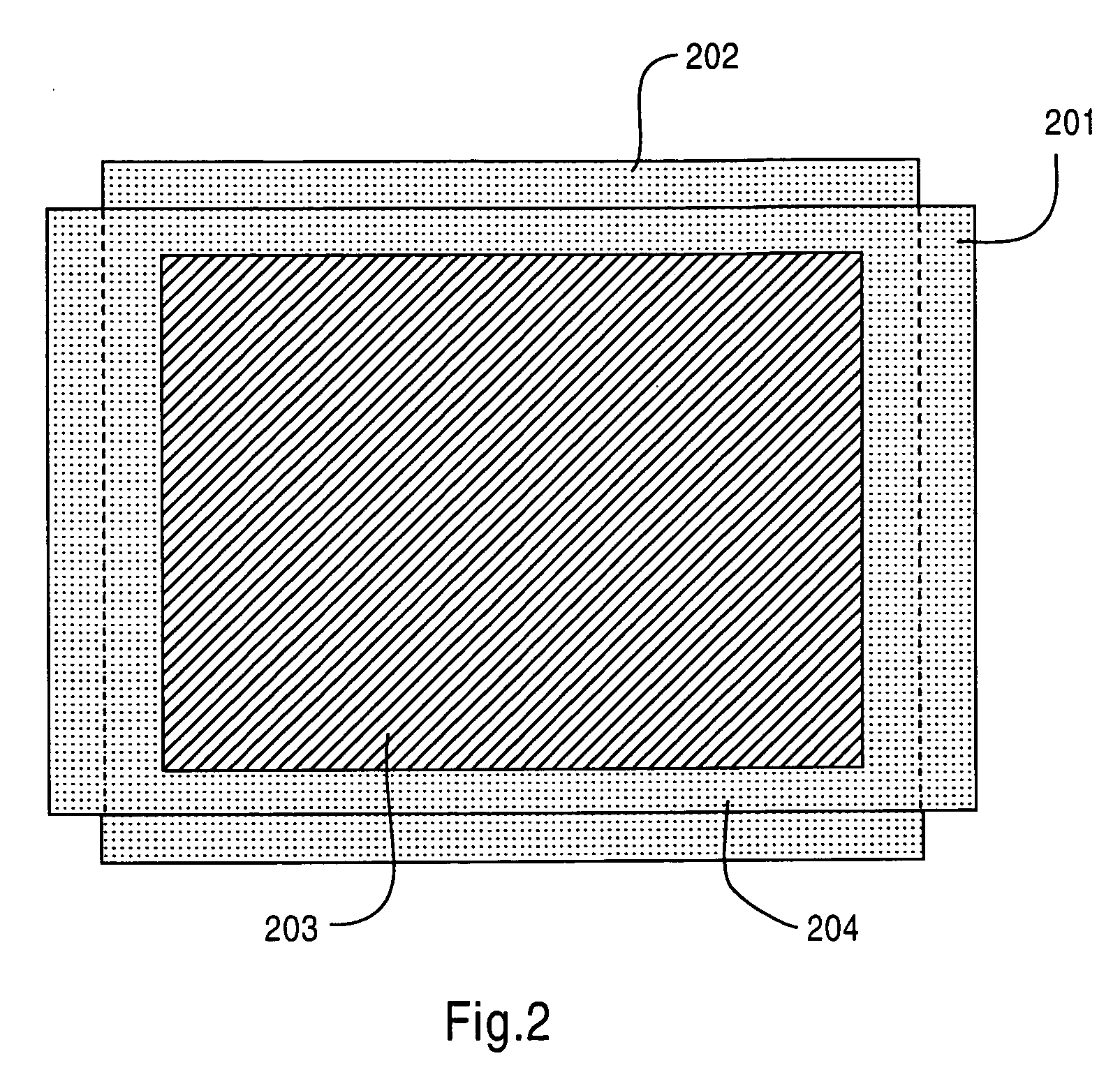
[0031] Accordingly, FIG. 3 illustrates a PDP 300 according to an embodiment of the present invention. The PDP 300 includes a chassis structure 301, which extends beyond a display portion 302 toward a non-display portion 303. The display portion 302 is that portion upon which a displayed image appears, as opposed to the non-display portion 303, where an image does not appear visible from the vantage point of a flat panel display viewer. A circuit framework structure 304, in this embodiment, includes a PCB 304a having circuit parts 304b. The PCB 304a is coupled to a chassis structure 301 by an attachment fastener structure 305. The attachment fastener structure 305 may be in various forms, e.g., securing screw, adhesive layer, etc. An IC 306 is disposed behind the n...


PUM


Abstract

In a Plasma Display Panel (PDP) apparatus, system and method including a circuit framework structure, a chassis structure coupled to the circuit framework structure, at least one thermal pad structure coupled to the chassis structure, a panel structure coupled to the at least one thermal pad structure and including a display portion and a non-display portion, an integrated circuit disposed behind said non-display portion of said panel structure, and at least one attachment fastener structure, which couples the structures, deleterious heat that is generated during operation of associated ICs can be efficiently dissipated. Thermal equilibration of the PDP may also be obtained, thus increasing the operational life of the PDP.

Description

BACKGROUND OF THE INVENTION [0001] 1. Field of the Invention [0002] The present invention relates to the field of flat-panel displays, particularly plasma display panels (“PDP”) technology, along with associated methods of heat dissipation and thermal management. [0003] 2. Related Art [0004] Traditionally, various electronic devices have utilized heat sink devices either integrally configured or attached to dissipate heat in thermally deleterious heat generating components in such devices. The same is true with flat-panel display modules, such as liquid crystal display (“LCD”) and PDP technologies, which generate enormous heat quantities. Heat sinks have been utilized to quickly but relatively inefficiently dissipate the heat generated in integrated circuits (“IC”). [0005] However, methods associated with heat sinks have several disadvantages. Heat sinks in flat-panel devices increase device costs, weight and dimensional thickness. All of these characteristics inevitably limit the a...

Claims


Application Information

Patent Timeline
Patent Type & Authority Applications(United States)
IPC IPC(8): H01J7/24
CPCH05K5/02H05K7/20963
Inventor LIN, YU-KAIWU, JIUN-HANSU, YAO-CHING
Owner AU OPTRONICS CORP
Why Eureka
Try Eureka