Multiple frequency detection system

a detection system and multi-frequency technology, applied in the field of electromagnetic fields, can solve the problems of affecting the safety of people from near magnetic field radiation, and the need to keep human exposure to near magnetic field radiation low,

Inactive Publication Date: 2006-07-20
CHECKPOINT SYST INC
View PDF5 Cites 59 Cited by
  • Summary
  • Abstract
  • Description
  • Claims
  • Application Information

AI Technical Summary

Benefits of technology

[0048] The preferred embodiments of the present invention specifically relate to a new generation of technologies which will allow the seamless integration of an almost ideal EAS function with an RFID function. While not being limited to a particular theory, the preferred embodimen...

Problems solved by technology

Lastly, the need to keep human exposure to near magnetic field radi...

Method used


Image

  • Multiple frequency detection system
  • Multiple frequency detection system
  • Multiple frequency detection system

Examples


Embodiment Construction

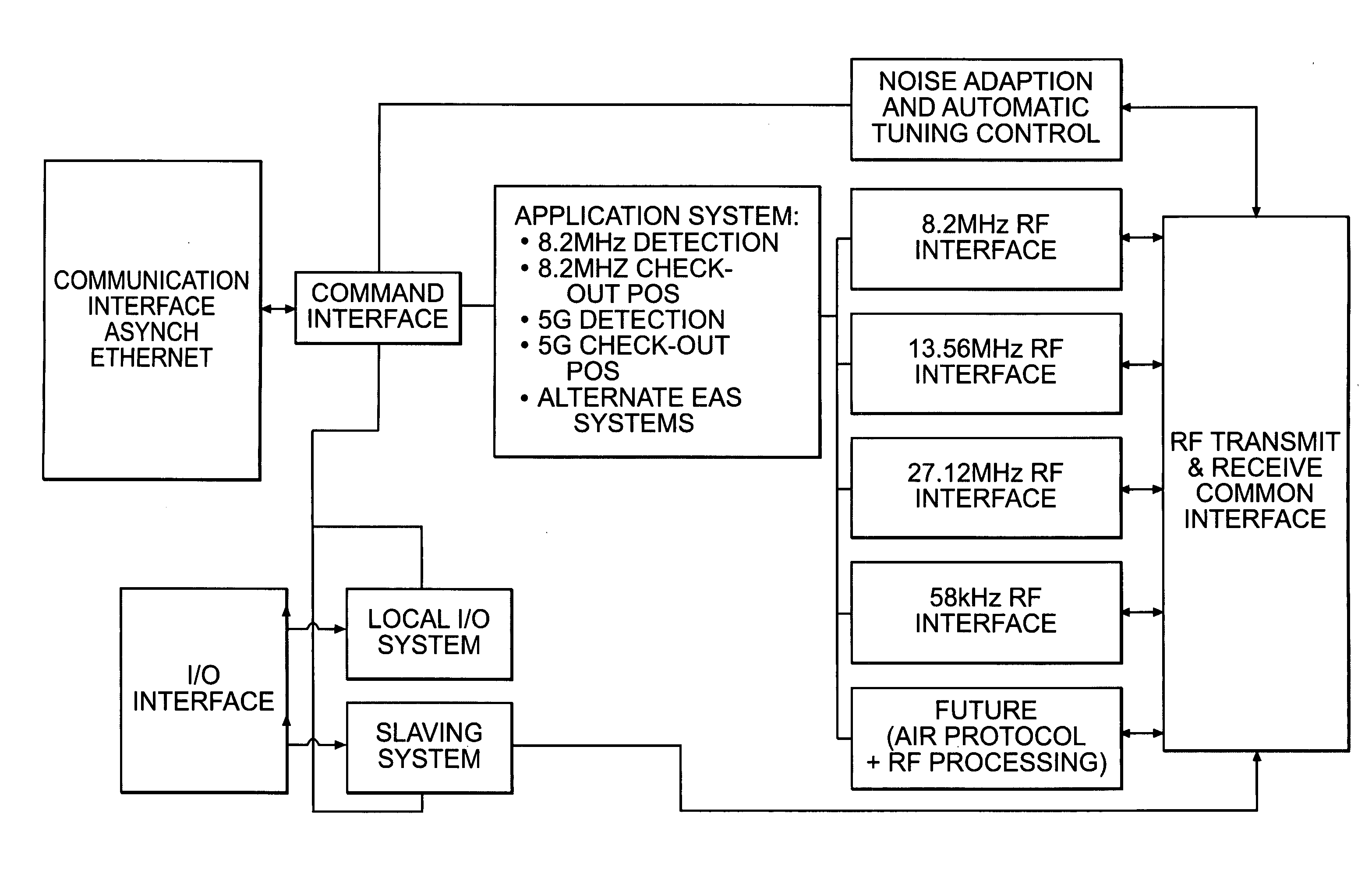
[0076] While not being limited to a particular theory, the present invention is described in a system preferably using HF type technologies, not UHF. The reason is two fold. The first is that UHF technologies are easily corrupted by proximity to conductive objects (i.e. shielding and body detuning). The second is that UHF frequencies are still not globally harmonized and likely will not be in the near future. While UHF technologies are not preferred, it is understood that the scope of the invention is not limited to HF type technologies and in fact includes UHF technologies.

[0077] The preferred offset target utilizes the 13.56 MHz HF Industrial, Scientific, and Medical (ISM) band as a carrier. This carrier could be used with existing RFID systems or standalone. The offset target is preferably a single resonator type which is tuned to a frequency higher or lower than the carrier bandwidth. Detection is of the pulse type measuring the ring down (exponent) from the target envelope and...


PUM


Abstract

A multiple frequency detection system allows the seamless integration of an almost ideal EAS function with an RFID function. While not being limited to a particular theory, the preferred embodiments integrate EAS technology at, for example, 8.2 MHz or 14 MHz, and RFID technology at, for example, 13.56 MHz in a common antenna package. The use of standard RFID frequencies as forcing functions will allow for the easy packaging of EAS with RFID and have a true roadmap of a scalable technology.

Description

FIELD OF INVENTION [0001] This invention relates to the electromagnetic field of radio frequency (RF) physics, and in particular, to loss prevention and security using radio frequency identification (RFID) and electronic article surveillance (EAS) technologies. BACKGROUND OF THE INVENTION [0002] The current technology uses a 8.2 MHz high frequency signal source to create a magnetic field in a bandwidth sufficient enough to match the design tolerance of the disposable targets which are built to resonant at a single frequency. The base technology of detection and deactivation has been the same for almost two decades and has reached a defacto-standard worldwide. This technology is based on the need to sell a recurring consumable to the customer in the form of a target placed on merchandize that can be detected by a security system at the perimeter of a protected area with some type of alarm that will notify store personnel if the target has not had its physical characteristics changed ...

Claims


Application Information

Patent Timeline
IPC IPC(8): H04Q5/22G08B13/14
CPCG08B13/2414G08B13/2417G08B13/242G08B13/2448G08B13/2482
Inventor ECKSTEIN, ERIC
Owner CHECKPOINT SYST INC
Why Eureka
Try Eureka