Variable transmissivity window system

a window system and variable technology, applied in the field of windows, can solve the problems of complex control of the transmissivity adjustment, impracticality of compiling the occupant to wear glasses,

Inactive Publication Date: 2006-07-20
HITACHI LTD
View PDF6 Cites 54 Cited by
  • Summary
  • Abstract
  • Description
  • Claims
  • Application Information

AI Technical Summary

Benefits of technology

[0008] In accordance with the present invention, the system can positively decide whether or not incoming light gives glare to the occupant according to ambient light level. When incoming light gives a glare to the occupant, the system modifies a transmissivity at a point on the windshield through which the glare giving light passes to avoid the glare while passing most information necessary for driving through the other area of the windshield.
[0009] When such light as to give glare to the occupant comes, the system modifies a threshold for lane departure warning, and controls vehicle in a non-acceleration mode, and displays a video of a scene around a light source as a glaring source, thus contributing to safe running.

Problems solved by technology

This impractically compels the occupant to wear the glasses.
Further, since the occupant wearing the glasses is moving at all times, this involves another problem that the transmissivity adjustment requires complex control.

Method used


Image

  • Variable transmissivity window system
  • Variable transmissivity window system
  • Variable transmissivity window system

Examples


embodiment 1

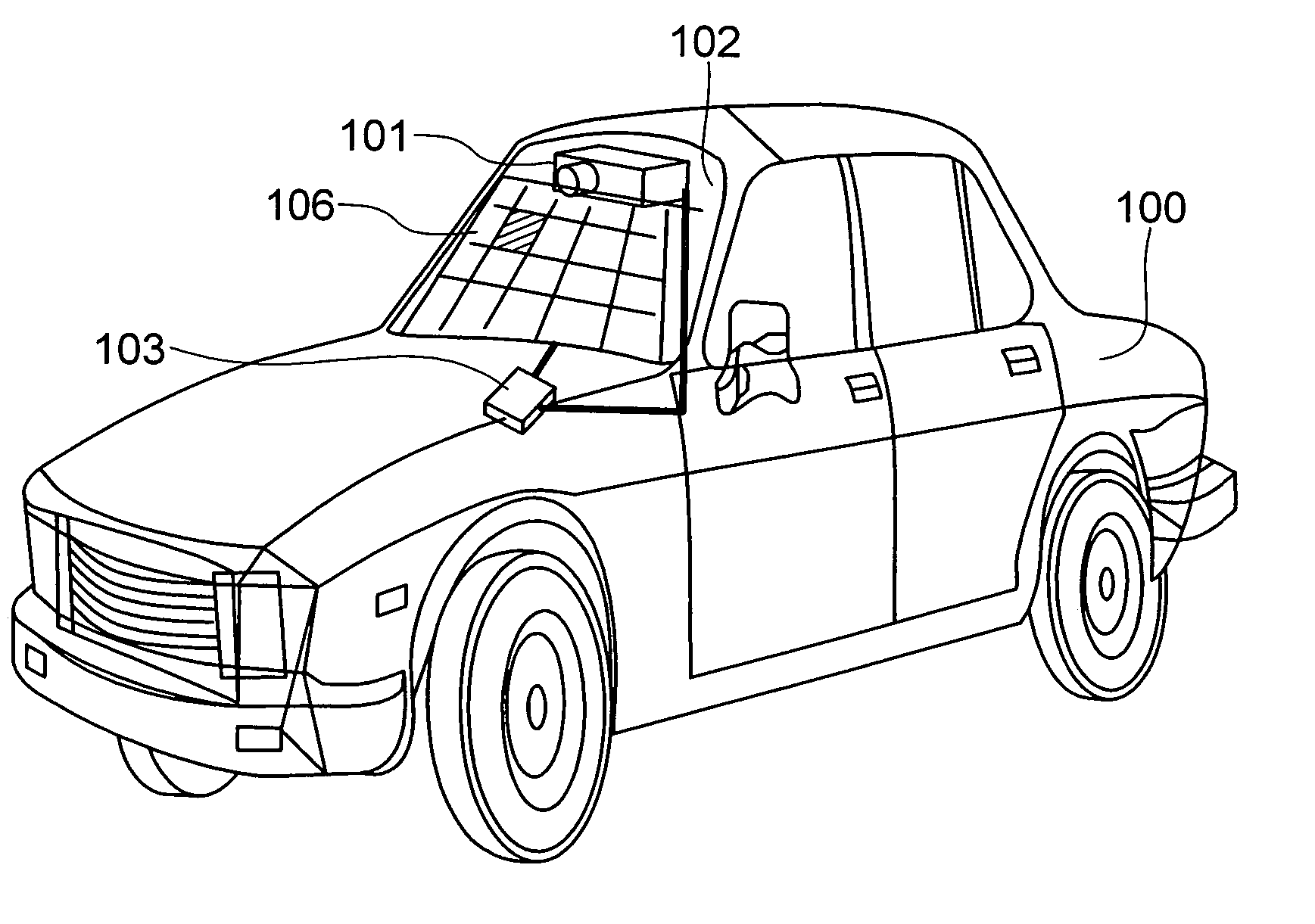
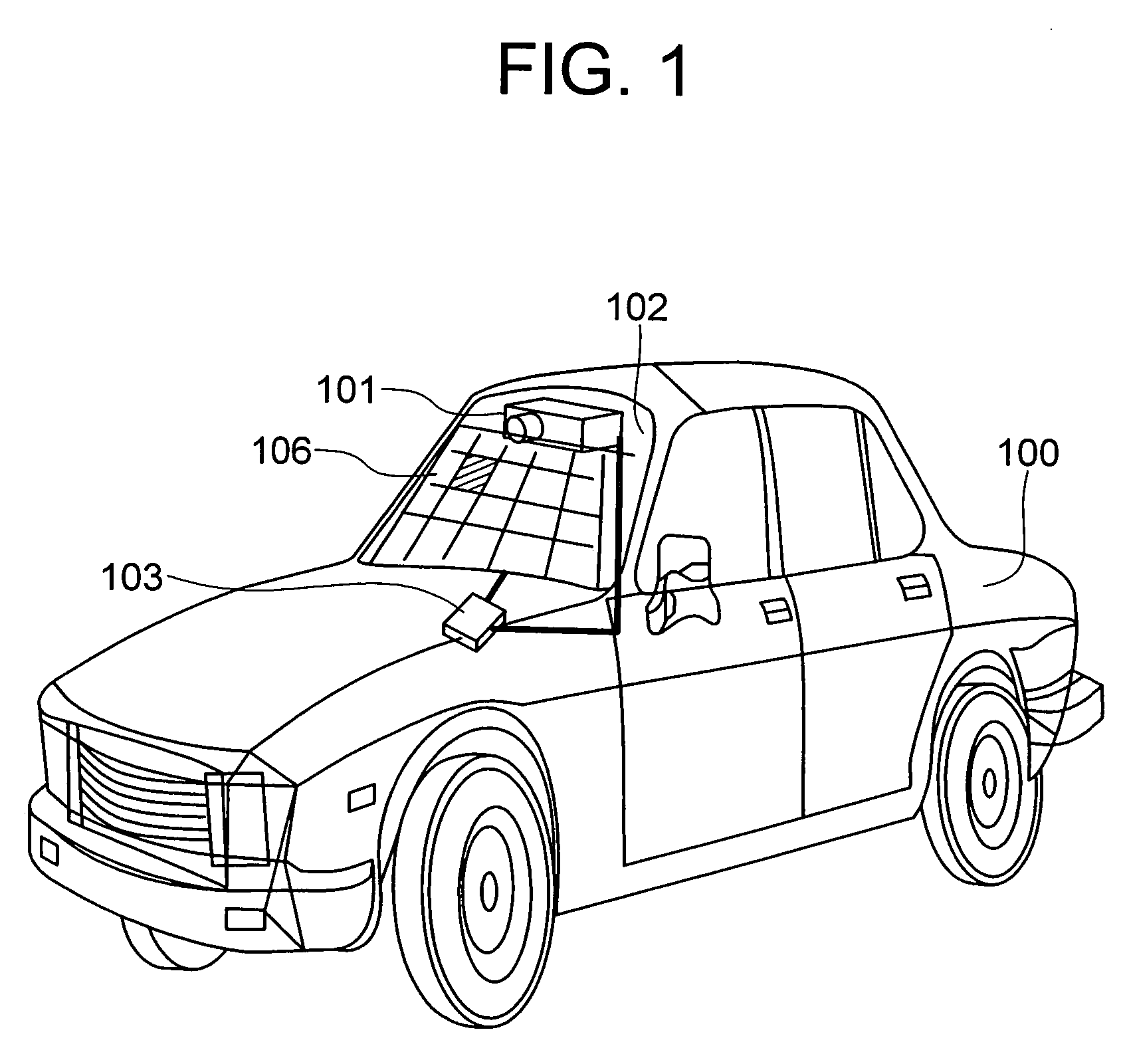
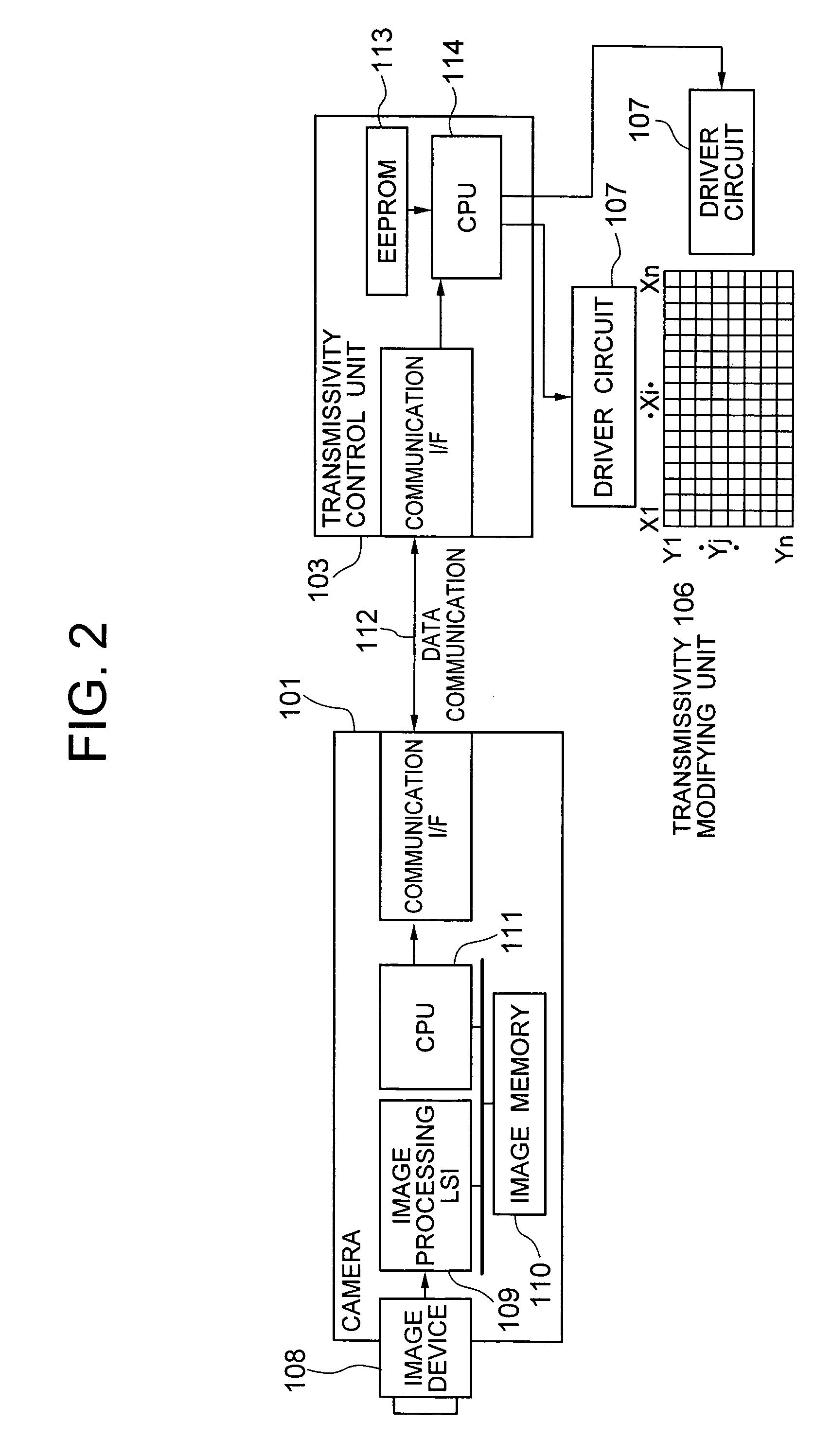
[0026]FIG. 1 shows a schematic arrangement of a variable transmissivity window system in accordance with a first embodiment of the present invention. FIG. 2 is a block diagram for explaining the operation of the variable transmissivity window system in accordance with the first embodiment. In the drawings, reference numeral 100 denotes a vehicle, numeral 101 denotes a camera, 102 denotes a windshield, 103 a transmissivity control unit, 106 a transmissivity modifying unit, 107 a driver circuit, 108 an image device, 109 an image processing LSI, 110 an image memory, 111 and 114 CPUs, 112 a data communication network, 113 an EEPROM, respectively.

[0027] In FIG. 1, the camera 101 is mounted on the ceiling of an interior chamber of the vehicle 100 to be oriented forward. The transmissivity control unit 103 for controlling the transmissivity of each of blocks into which the windshield is divided, is provided within the vehicle 100. More specifically, the windshield 102 is divided into smal...

embodiment 2

[0041]FIG. 3 shows a schematic arrangement of a variable transmissivity window system in accordance with a second embodiment of the present invention. FIG. 4 is a block diagram for explaining the operation of the variable transmissivity window system of the second embodiment. In the FIGS. 3 and 4, the same explanation as in FIGS. 1 and 2 is applied to constituent elements (having the same reference numerals) common to the first embodiment of FIGS. 1 and 2.

[0042] The second embodiment, in addition to the constituent elements of the first embodiment, includes a vehicle control unit 104, a seat position measuring unit 120, a camera 116 for vehicle interior image pickup (also referred to the interior-pointed camera), a video display unit 105, and a transmissivity modification position change switch 117. The seat position measuring unit 120 has a pressure sensor, a seat tilt sensor, a forward / backward seat position sensor, and a headrest position sensor, as shown in FIG. 9. The seat pos...


PUM

PropertyMeasurementUnit
sizeaaaaaaaaaa
accelerationaaaaaaaaaa
thresholdaaaaaaaaaa

Abstract

The variable transmissivity window system comprises a camera for detecting light from a light source, a transmissivity control unit for controlling the transmissivity of light passed through the windshield, and a transmissivity modifying unit for modifying the transmissivity of each of blocks into which the windshield is divided. The camera calculates light source information including the direction, size and intensity of the light source. The transmissivity control unit calculates a position of the windshield block for the transmissivity to be modified, a range of the position thereof for the transmissivity to be modified, and a value for the transmissivity. The imaging unit decides whether or not the light source gives glare to the occupant, and when the imaging unit decides that the light source gives glare to the occupant, the imaging unit changes a glare decision threshold according to an ambient light level outside the vehicle.

Description

BACKGROUND OF THE INVENTION [0001] The present invention relates to a window system which can arbitrarily modify the transmissivity of a window or windshield of a vehicle according to the ambient condition of the vehicle. [0002] When sunlight comes into a vehicle, the occupant of the vehicle has conventionally used a sun visor to shield occupant's eyes from direct sunlight or glare. However, the use of the sun visor involves troublesome problems that the occupant cannot also see necessary light other than the undesirable direct sun light and cannot know information necessary for driving, and that the occupant is also required to adjust the position of the sun visor for it. [0003] As one of prior arts for improving such circumstances, it is proposed to adjust the transmissivity of a car windshield to avoid glare, e.g., as shown in JP-A-5-203906. As disclosed in JA-5-203906, an optical element is mounted in the vicinity of occupant's eye so that transmission light incident to the opti...

Claims


Application Information

Patent Timeline
Patent Type & Authority Applications(United States)
IPC IPC(8): G02F1/15
CPCB60J3/04Y02T10/88
Inventor FURUSAWA, ISAOKASUYA, HIROYUKIOUCHI, KATSUO
Owner HITACHI LTD
Why Eureka
Try Eureka