Enhanced nail clippers and system thereof

a nail clipper and clipper technology, applied in the field of nail clippers, can solve the problems of animal pain, difficult to see the quick end, profuse wound bleeding, etc., and achieve the effect of better manicuring an animal's nail

Inactive Publication Date: 2006-07-20
HOPKINS TIMOTHY PAUL +2
View PDF17 Cites 28 Cited by
  • Summary
  • Abstract
  • Description
  • Claims
  • Application Information

AI Technical Summary

Benefits of technology

[0011] A fourth embodiment is a method for better manicuring an animal's nail. The method includes: aligning a lighting element to a target nail such that the target nail is transilluminated to visually expose the location of the animal's quick; positioning a cutting instrument to a desirable location, relative to the quick, of the target nail; and cutting the target nail with the cutting instrument.

Problems solved by technology

If an owner or groomer accidentally cuts the quick of the nail (the vein), not only does it cause the animal pain, but the wound bleeds profusely.
For animals with dark colored nails it is very difficult to see where the quick ends.
Although this may help keep the user from cutting the nails too short, it does not identify the location of the quick and, thus, the possibility of either cutting the quick or leaving the nails too long remains.
The Jeong patent is generally focused on nail clippers to be used for human nails, and so fails to recognize the need to clip animal nails as close to the quick as possible.
As such, there remains an unsatisfied need in the market for nail clippers that better provide for clipping animals' nails, given the unique features of such nails as just previously mentioned.

Method used


Image

  • Enhanced nail clippers and system thereof
  • Enhanced nail clippers and system thereof
  • Enhanced nail clippers and system thereof

Examples


first embodiment

[0028] the enhanced nail clipper system 100 includes a lighting element 115 confined within a lighting housing 110. The lighting housing 110, in this embodiment is mounted atop a first blade member 102 and positioned in such a way as to transilluminate a target nail when placed between the cutting edges 104 and 105 of the nail clipper 101.

[0029] The lighting element 115 is powered by a wire lead 120 running from the lighting housing 110 to a toggle switch 130. In this case the toggle switch 130 is mounted on an interior portion of the handle 108 of the nail clipper 101. The toggle switch 130 is wired to a power supply 140.

[0030] The lighting element 115 could utilize a number of illumination technologies. Light emitting diodes (LEDs), incandescent, and laser are all types of lighting elements that could be used to transilluminate the target nail. It should be construed by those having ordinary skill in the art that any of these lighting technologies mentioned and those not mentione...

second embodiment

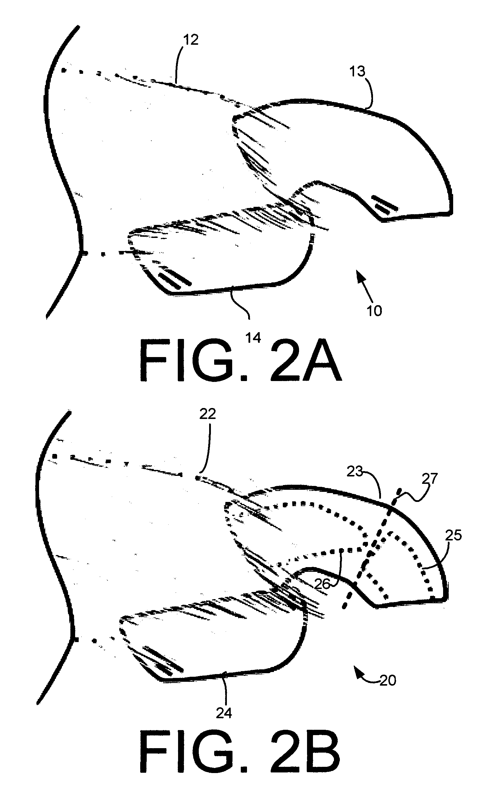
[0036]FIG. 4B is a perspective view illustrating an enhanced nail clipper 250 in accordance with the present invention Nail clipper 250 is based upon a second type of animal nail clipper prevalent in the market today. Nail clipper 250, is comprised of a first handle 258 and a second handle 259 that are movable with respect to each other in a first plane of motion in order to provide relative movement between a first cutting blade 252 and a stationary anvil 253. Cutting blade 252 moves with respect to anvil 253 in a second plane of motion, which in this embodiment, is substantially perpendicular to the first plane of motion.

[0037] Stationary anvil 253 is molded such that a hole exists 251. The hole 251 is positioned to receive a target nail, whereby the first cutting blade 252 will sweep across and cut the target nail when the first and second handles 258 and 259 are squeezed together. A biasing spring (not shown) may be positioned between the first and second handles 258 and 259 to ...

third embodiment

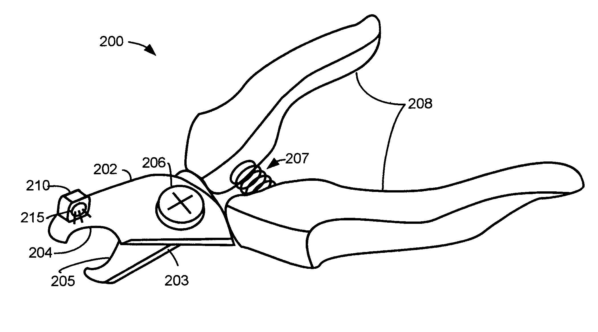
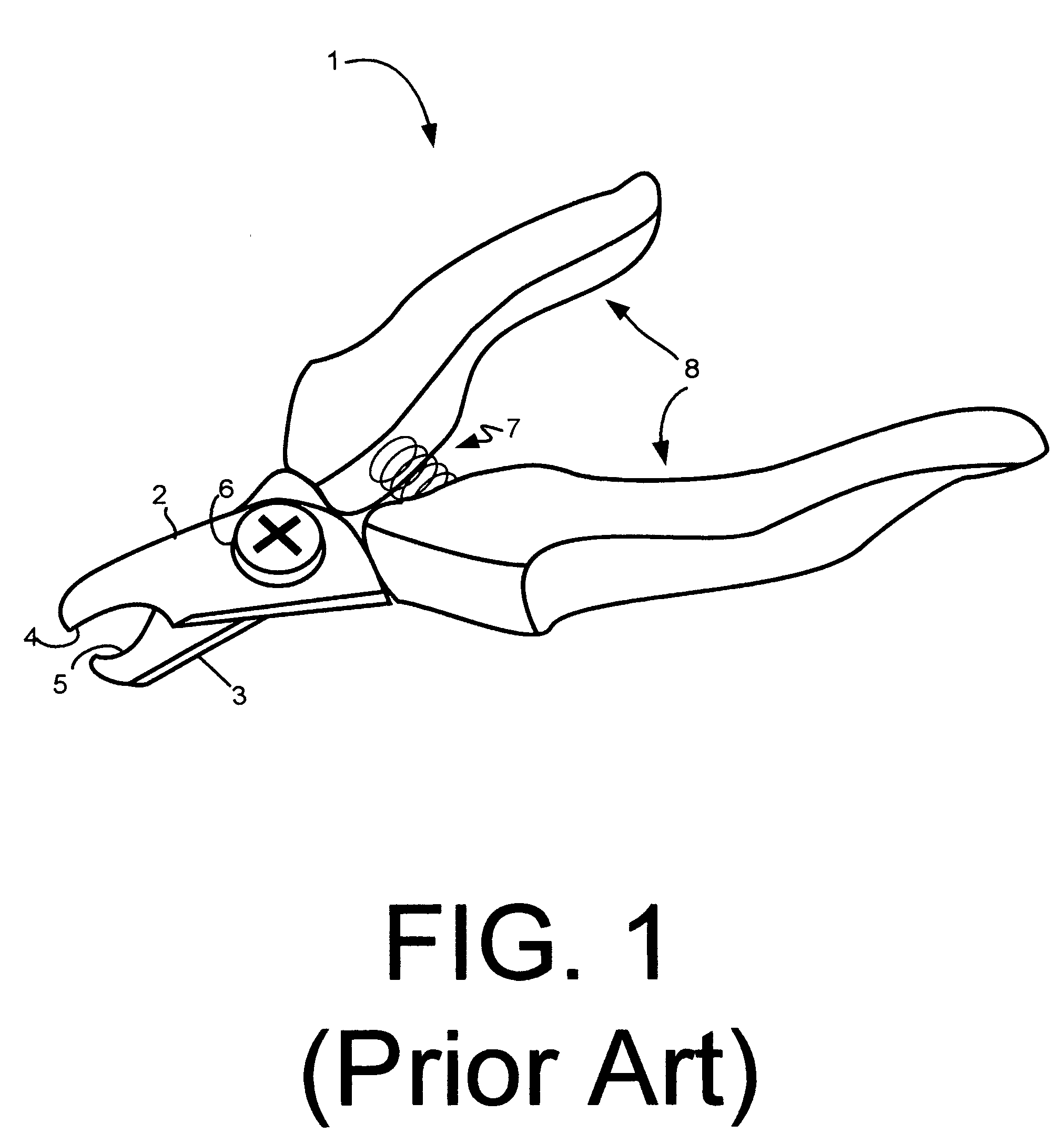
[0039]FIG. 5 is a perspective view illustrating the enhanced nail clipper 300 in accordance with the present invention. Again, a conventional nail clipper is the basis of the enhanced nail clipper 300. Nail clipper 300 includes handles 308 coupled with opposing cutting blades 302 and 303, each with cutting edges 304 and 305. When the handles are squeezed together, the cutting edges, 304 and 305, close against each other in a first plane, thus cutting a target nail. A biasing spring 307 can be used to bias the handles 308 in an open position.

[0040] Enhanced nail clipper 300 includes a lightpipe 310 positioned to transilluminate a target nail to be positioned by the user between the cutting edges 304 and 305. A fiber optic cable 320, or some other means, is used to direct light from a lighting element 350 to the lightpipe 310. The lighting element 350, in this embodiment, is embedded in a cavity 309 of one of the handles 308.

[0041] Coupled to the lighting element 350 is a push-button...


PUM


Abstract

Systems, methods, and devices for better manicuring a patient's nails are disclosed. A representative embodiment is a system that includes a lighting element for transilluminating the nail, a power supply for powering the lighting element, and a switch for activating the lighting element.

Description

CROSS-REFERENCE TO RELATED APPLICATION [0001] This application claims priority to copending U.S. provisional application entitled, “Enhanced Nail Clippers,” having Ser. No. 60 / 644,674 filed Jan. 18, 2005, which is entirely incorporated herein by reference.FIELD OF THE INVENTION [0002] The present invention generally relates to nail clippers. More specifically, the invention relates to nail clippers for animals, such as dogs and cats. DESCRIPTION OF THE RELATED ART [0003] Some animals, such as dogs, have veins present in the center and toward the base of their nails. If an owner or groomer accidentally cuts the quick of the nail (the vein), not only does it cause the animal pain, but the wound bleeds profusely. For animals with light colored nails, the quick can often be seen with the naked eye. For animals with dark colored nails it is very difficult to see where the quick ends. It is important to cut an animal's nail as close to the quick as possible because the quick will grow ove...

Claims


Application Information

Patent Timeline
Patent Type & Authority Applications(United States)
IPC IPC(8): B25B23/18
CPCA01K13/00A01K17/00A45D29/02
Inventor HOPKINS, TIMOTHY PAULDYKSTRA, DANIEL RUSSSIRMANS, GREGORY JAMES
Owner HOPKINS TIMOTHY PAUL
Why Eureka
Try Eureka