Connector assembly clip

a connector and assembly technology, applied in the field of optical fiber connectors, to achieve the effect of simple and robust clip, simple, but effective, and facilitate the assembly of two or more identical connectors

Inactive Publication Date: 2006-07-20
TE CONNECTIVITY CORP
View PDF13 Cites 15 Cited by
  • Summary
  • Abstract
  • Description
  • Claims
  • Application Information

AI Technical Summary

Benefits of technology

[0011] The present invention provides for a connector system which facilitates the assembly of two or more identical connectors using a simple and robust clip. Specifically, the system employs a simple, but effective, clip which engages a contoured section of the housings of standard simplex connectors to hold two or more of them securely in place.

Problems solved by technology

First, it uses identical simplex connectors as building blocks for larger, more-complex connector assemblies (e.g., duplex and quad connector assemblies).

Method used


Image

  • Connector assembly clip
  • Connector assembly clip
  • Connector assembly clip

Examples


Embodiment Construction

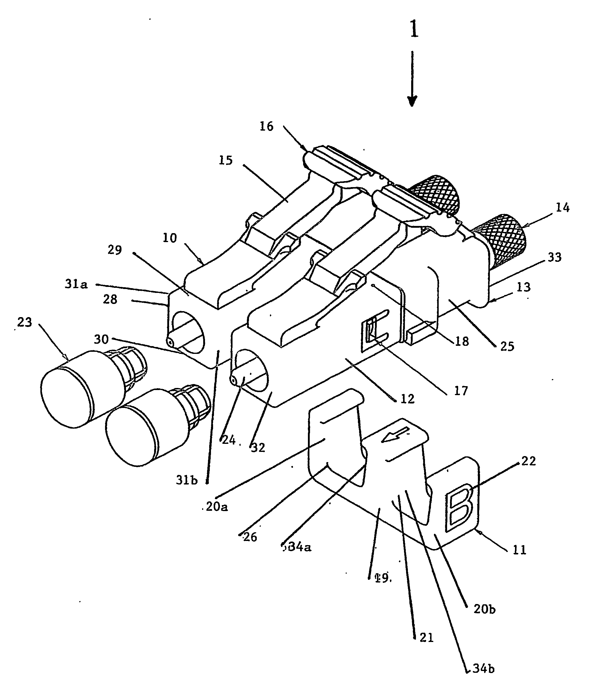
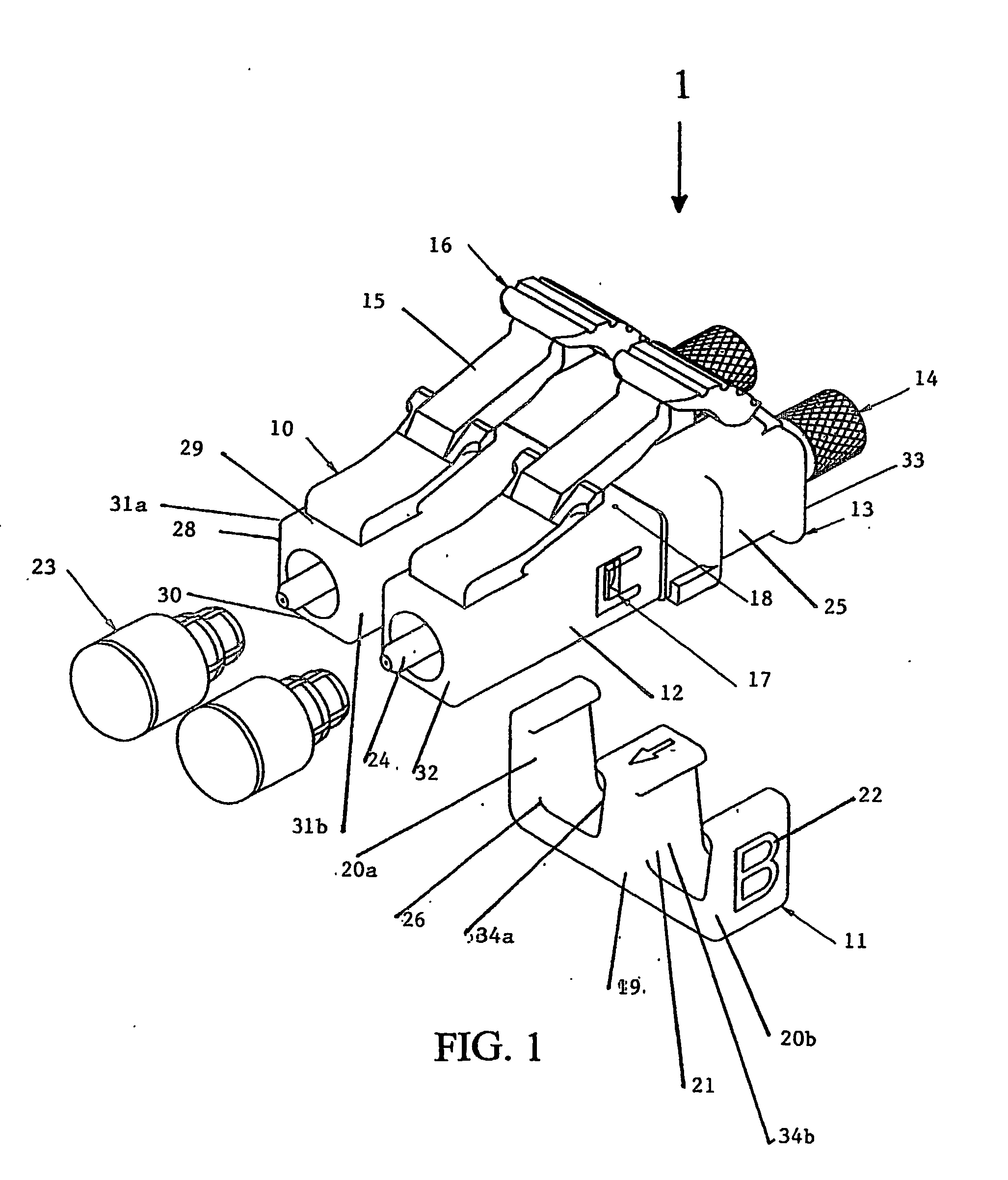
[0021] Referring to FIG. 1, a preferred embodiment of the connector system of the present invention is shown. The connector assembly 1 comprises a plurality of identical simplex connectors 10. Each connector comprises a generally rectangular housing 28 having a top 29, a bottom 30, sides 31a, 31b and two ends-a front or plug end 32 and a back or cable end 33. The plug end 32 is suitable for insertion into a mating receptacle (not shown) while the cable end 33 is adapted for receiving and securing an optical cable (not shown). The housing 28 has a recess 25 along each of the two sides 31a, 31b. The connector assembly also comprises a clip 11 for holding the plurality of connectors 10 together in a side-by-side relationship. The clip has a bottom portion 19, first and second end walls 20a, 20b extending substantially perpendicularly from the bottom portion 19, and one or more intermediate portions 21 also extending substantially perpendicularly from the bottom portion 19 between the f...


PUM


Abstract

An optical connector assembly comprising (a) a plurality of identical connectors, each connector being connected to a jacketed optical cable, each connector comprising a generally rectangular housing having a top, a bottom and two sides, and having a plug end for insertion into a mating receptacle and a cable end for receiving an optical cable, the housing having a recess along each of the two sides; and (b) a clip holding the plurality of connectors together in a side-by-side relationship, the clip having a bottom portion, first and second end walls extending perpendicularly from the bottom portion, and one or more intermediate portions extending perpendicularly from the bottom portion between the first and second end walls, each of the one or more intermediate portions having a first face facing the first end wall and a second face facing the second end wall, wherein the first end wall and a first face of one of the one or more intermediate portions are received in the recess of one of the connectors and the second end wall and a second face of one of the one or more intermediate walls are received in the recess of another of the connectors such that the connectors are held in a side-by-side arrangement.

Description

REFERENCE TO RELATED APPLICATION [0001] This application claims priority to U.S. Provisional Application No. 60 / 452,868 which was filed on Mar. 6, 2003 and is hereby incorporated by reference.FIELD OF INVENTION [0002] The present invention relates generally to optical fiber connectors, and, more specifically, to duplex connector assemblies. BACKGROUND OF INVENTION [0003] Optical fiber connectors are an essential part of substantially all optical fiber communication systems. For instance, such connectors are used to join segments of fiber into longer lengths, to connect fiber to active devices such as radiation sources, detectors and repeaters, and to connect fiber to passive devices such as switches and attenuators. The principal function of optical fiber connectors is to hold an optical fiber such that its core is axially aligned with the optical path of the device to which the connector is mating (herein “mating device”). This way, the light from one fiber is optically coupled to ...

Claims


Application Information

Patent Timeline
Patent Type & Authority Applications(United States)
IPC IPC(8): G02B6/36G02B6/38
CPCG02B6/3825G02B6/3879G02B6/3893
Inventor ERDMAN, DAVID DONALDGURRERI, MICHAEL LAWRENCE
Owner TE CONNECTIVITY CORP
Why Eureka
Try Eureka