Feedforward spur cancellation approach using low IP amplifier

a low-ip amplifier and spurious signal technology, applied in the direction of amplifier modification, antenna, electric long antenna, etc., can solve the problems of high linearity error amplifier, insufficient spurious signal production, and increase the complexity of circui

Active Publication Date: 2006-07-20
NORTHROP GRUMMAN SYST CORP
View PDF36 Cites 71 Cited by
  • Summary
  • Abstract
  • Description
  • Claims
  • Application Information

AI Technical Summary

Problems solved by technology

Nonlinearities within the power amplifier introduce signal harmonics, intermodulation products and other distortions and spurious counterparts of the RF signal that cause interfering signals to other frequency channels.
These problems include the requirement of a large number of directional couplers and signal splitters to sample the RF signal at the input, after the power amplifier 18, and at the output of the circuit 10 that increase the complexity of the circuit 10.
Another disadvantage includes the requirement of the high linearity error amplifier 26 so that the feed forward path 16 does not produce significant additional spurious signals from the high power amplification process.

Method used


Image

  • Feedforward spur cancellation approach using low IP amplifier
  • Feedforward spur cancellation approach using low IP amplifier
  • Feedforward spur cancellation approach using low IP amplifier

Examples


Embodiment Construction

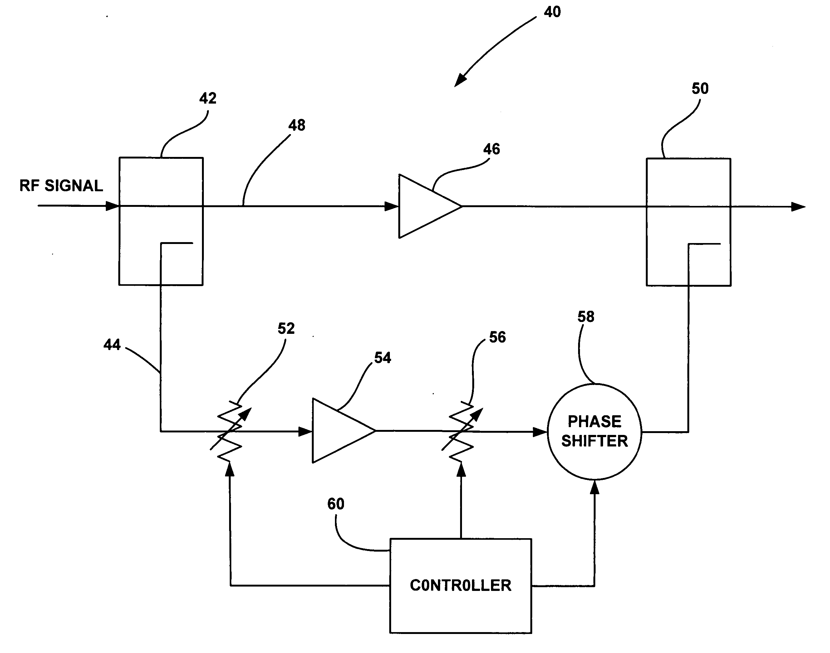
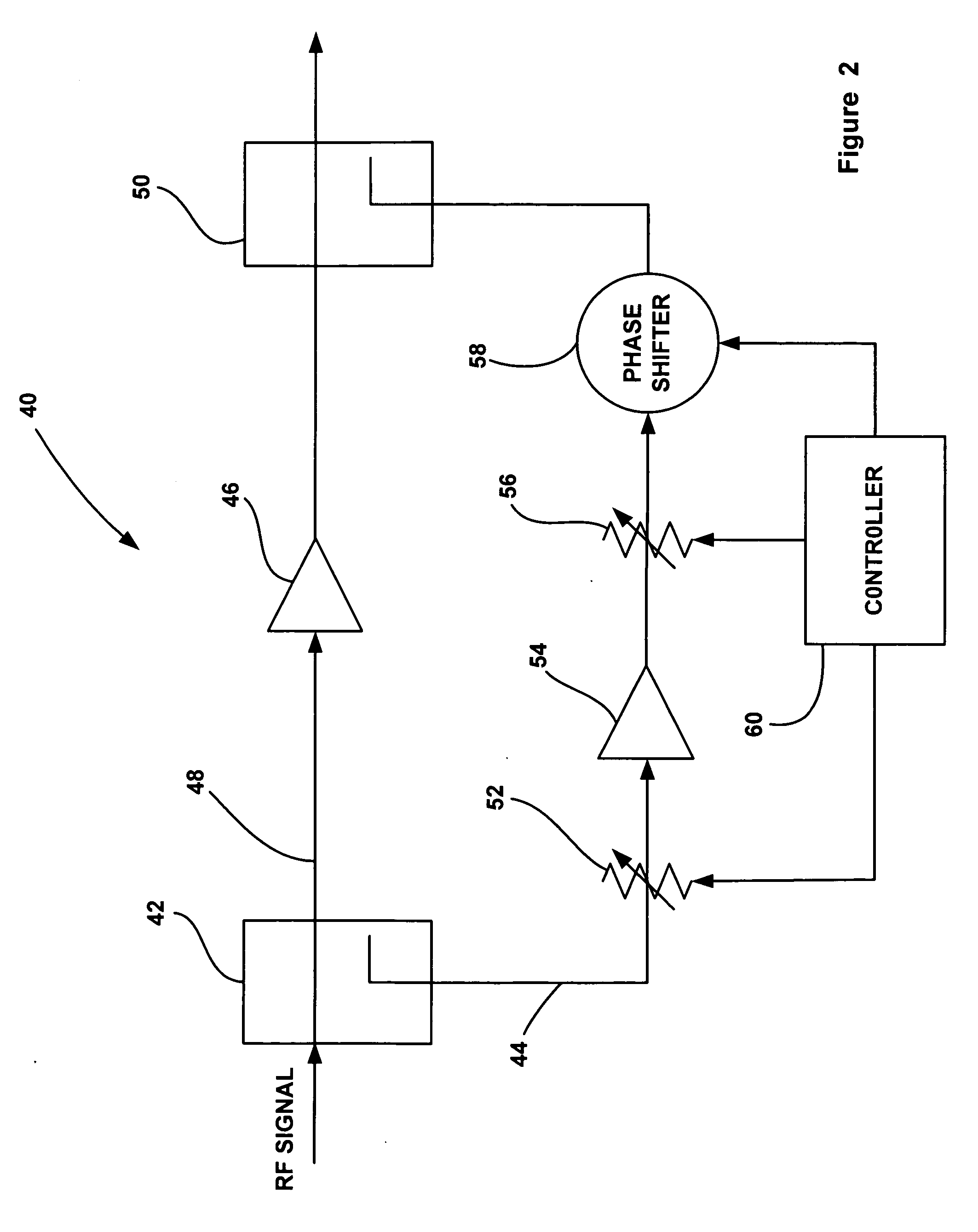
[0016] The following discussion of the embodiments of the invention directed to an RF power amplifier employing a feed forward error correction loop having two variable attenuators is merely exemplary in nature, and is in no way intended to limit the invention or its applications or uses.

[0017]FIG. 2 is a schematic diagram of a power amplifier circuit 40, according to an embodiment of the present invention, for use in a transmitter or the like. An RF signal to be transmitted having a certain main center frequency is sent through a splitter or directional coupler 42 that samples off a portion of the RF signal and applies it to a feed forward error correction loop 44. Most of the RF signal propagates through the coupler 42 to be amplified by a linear main power amplifier 46 on a main signal path 48. The power amplifier 46 can be any power amplifier suitable for the purposes described herein, such as a high gain, high IP3 (60 dBc) amplifier providing 10 dB of signal gain.

[0018] As di...


PUM


Abstract

A power amplifier circuit (40) that includes an error correction loop (44) having a lower IP3 error correction amplifier (54) than a main power amplifier (46) in a main signal path (48). A first attenuator (52) in the error loop (44) attenuates the RF signal, and provides more attenuation of intermodulation products in the RF signal and about the same attenuation for a main frequency of the RF signal for each dB of attenuation. The error amplifier (54) amplifies the attenuated RF signal from the first attenuator (52). A second attenuator (56) in the error loop (44) attenuates the RF signal from the error correction amplifier (54). A phase shifter (58) phase shifts the RF signal from the second attenuator (56). A coupler (50) couples the amplified RF signal and the phase shifted RF signal to cancel out intermodulation products in the amplified RF signal.

Description

BACKGROUND OF THE INVENTION [0001] 1. Field of the Invention [0002] This invention relates generally to a power amplifier employing a technique for spurious signal cancellation and, more particularly, to a power amplifier employing a feed forward error correction amplifier having a low IP3 value for generating greater magnitude intermodulation products to cancel spurious signals in an RF signal. [0003] 2. Discussion of the Related Art [0004] Communications systems that transmit RF signals carrying information typically employ linear power amplifiers to amplify the transmit signal so that it has enough power to be received and deciphered by a receiver at a distant location. Nonlinearities within the power amplifier introduce signal harmonics, intermodulation products and other distortions and spurious counterparts of the RF signal that cause interfering signals to other frequency channels. The signal harmonics can typically be filtered out, but the intermodulation products and other ...

Claims


Application Information

Patent Timeline
Patent Type & Authority Applications(United States)
IPC IPC(8): H01Q11/12
CPCH03F1/3223
Inventor KINTIS, MARK
Owner NORTHROP GRUMMAN SYST CORP
Why Eureka
Try Eureka