Audio and video buffer synchronization based on actual output feedback

a buffering and audio technology, applied in the field of buffering audio and video, can solve the problems of insufficient synchronization of the streamed data for each endpoint to process in order to stay synchronized, different amounts of delay on each endpoint, and high user experien

Active Publication Date: 2006-07-20
MICROSOFT TECH LICENSING LLC
View PDF46 Cites 79 Cited by
  • Summary
  • Abstract
  • Description
  • Claims
  • Application Information

AI Technical Summary

Benefits of technology

[0011] An external adjustment and delay mechanisms may be used to synchronize two or more endpoints. With respect to delay, the source device or endpoint (sink) may be instructed by the synchronization mechanism to add more or less delay before transmission or playback, to optimize the buffering of content in the sink device. This delay may compensate for delays in networking, including source data transmission and feedback. In general, the synchronization mechanism matches up the audio signal from the source to the content that has been decoded and read from the remote playback buffer, to provide an appropriate delay for synchronized playback of the AV content.

Problems solved by technology

Buffering inherently includes some amount of delay.
A different problem results when multiple output endpoints are being used.
In such a situation, the buffering can cause different amounts of delay on each endpoint.
As can be readily appreciated, when a user can simultaneously hear (or see) two signals that are out of synchronization, a highly annoying user experience results.
Inserting synchronization-related codes such as timing signals or the like into the streamed data for each endpoint to process in order to stay synchronized is not an adequate solution in many instances.
For one, there are numerous device manufacturers, and no existing transmission protocol standards allow for the transmission of such codes.
In the event that such a standard is developed, it would not work with legacy endpoints, and would be costly to implement in many circumstances.
The mechanism may desirably require limited responsibility and expense at the endpoint.

Method used


Image

  • Audio and video buffer synchronization based on actual output feedback
  • Audio and video buffer synchronization based on actual output feedback
  • Audio and video buffer synchronization based on actual output feedback

Examples


Embodiment Construction

Exemplary Operating Environment

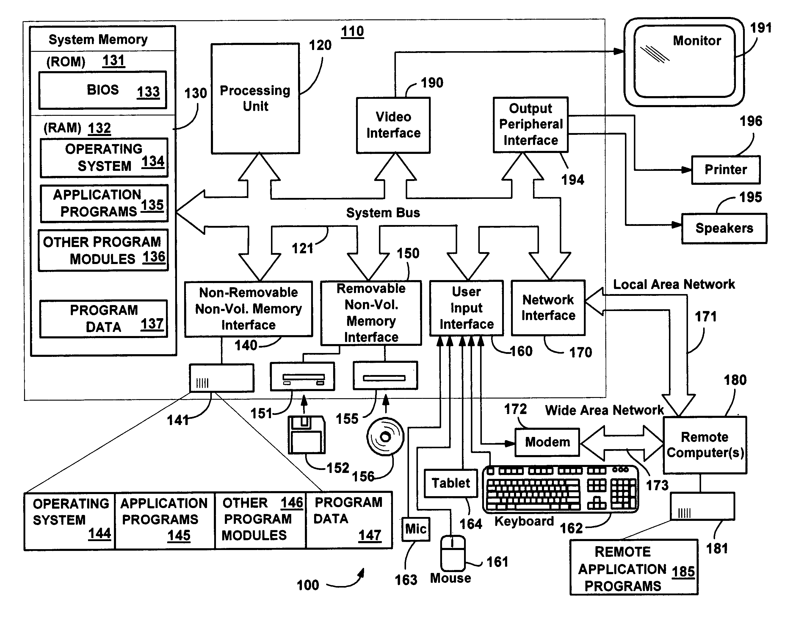
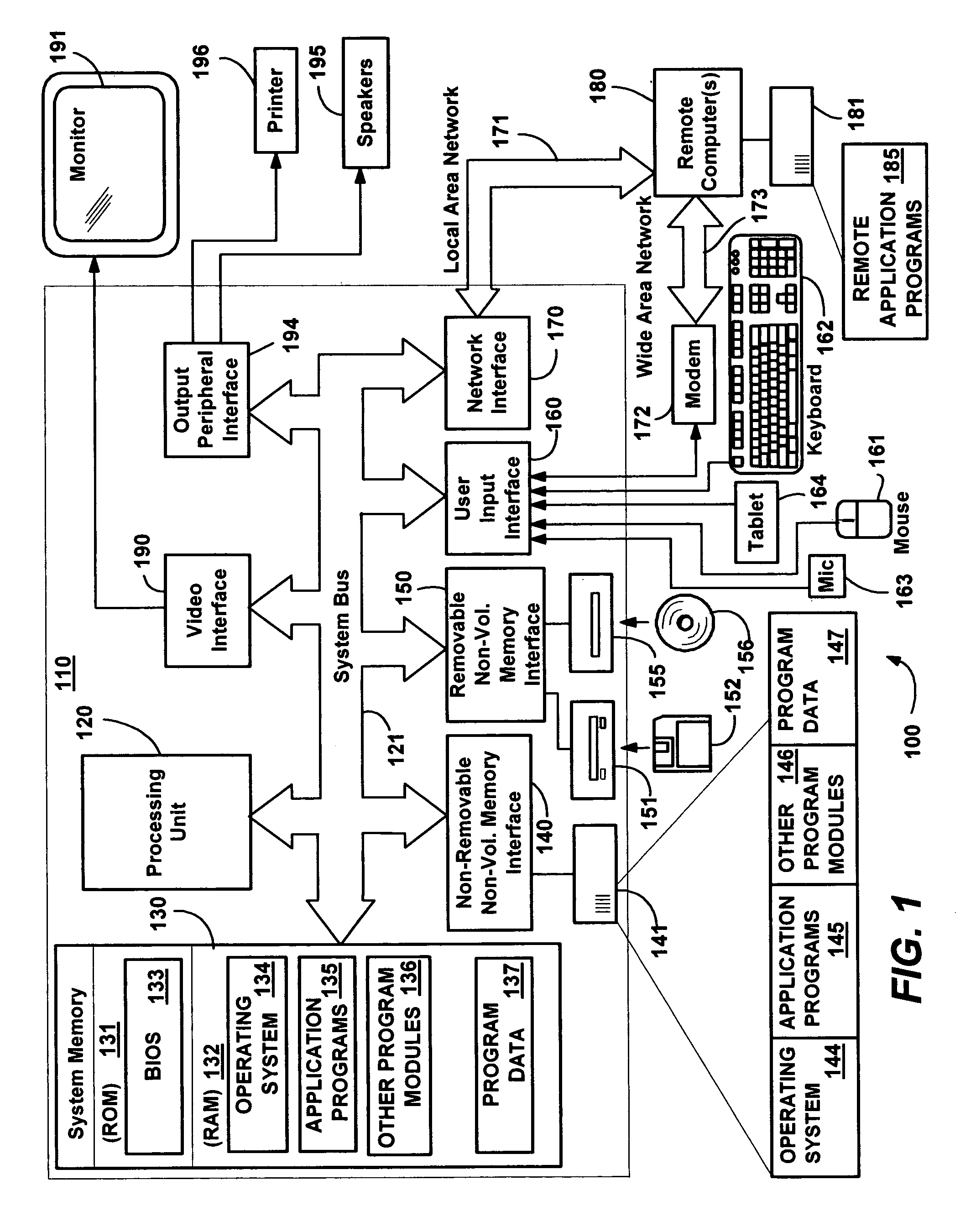
[0020]FIG. 1 illustrates an example of a suitable computing system environment 100 on which the invention may be implemented. The computing system environment 100 is only one example of a suitable computing environment and is not intended to suggest any limitation as to the scope of use or functionality of the invention. Neither should the computing environment 100 be interpreted as having any dependency or requirement relating to any one or combination of components illustrated in the exemplary operating environment 100.

[0021] The invention is operational with numerous other general purpose or special purpose computing system environments or configurations. Examples of well known computing systems, environments, and / or configurations that may be suitable for use with the invention include, but are not limited to: personal computers, server computers, hand-held or laptop devices, tablet devices, multiprocessor systems, microprocessor-based systems, ...


PUM


Abstract

A method and system for keeping endpoints such as speakers and displays synchronized via feedback based on the actual output of the endpoints. A source of audiovisual content transmits corresponding digital data to one or more endpoints, such as over a home network, where it may be buffered and/or decoded for playback. Microphones or the like sense actual (post-buffering/decoding) output from one or more endpoints and feed it back to a synchronization mechanism. The synchronization mechanism employs pattern matching or similar techniques to determine whether and how to adjust the timing of endpoints to synchronize their actual outputs. Synchronization may be accomplished by controllably delaying transmission and/or other processing, by controllably changing the rate of advancing in a buffer, and/or by jumping ahead in a buffer. The synchronization mechanism may adjust multiple endpoints, e.g., when limited buffer size limits the amount of adjustment a single device can provide.

Description

FIELD OF THE INVENTION [0001] The invention relates generally to computer networks that transmit audio and video signals, and more particularly to buffered audio and video. BACKGROUND OF THE INVENTION [0002] Contemporary media systems employ digitally compressed and transported audio and video streams, which typically require buffering during encoding and transmitting at the source and buffering for receiving and decoding at the destination. Buffering inherently includes some amount of delay. In a situation where the media system directly connects to a single endpoint such as a television and / or speakers, there are various adequate solutions to problem of synchronizing the audio output with the video output, because the same endpoint device buffers both sets of data. [0003] A different problem results when multiple output endpoints are being used. For example, consider the same audio being played back on a personal computer and also transmitted to a stereo system in the next room, o...

Claims


Application Information

Patent Timeline
Patent Type & Authority Applications(United States)
IPC IPC(8): G06F17/24
CPCG11B27/10H04N21/4135H04N21/42203H04N21/4307H04N21/4325H04N21/43615H04N21/4394H04N21/44008H04N21/44231H04N21/6332H04N21/654H04N21/43072
Inventor PANABAKER, RUSTON J.D.CHANDLEY, ADRIAN
Owner MICROSOFT TECH LICENSING LLC
Why Eureka
Try Eureka