System and Method for Time Synchronization in a Communication Network

a communication network and time synchronization technology, applied in the field of data communication, can solve the problems of increasing synchronization errors, controller input cannot be directly obtained at any instant, and the input of controllers becomes outdated, so as to improve the estimation of the reference clock time at individual network nodes

Inactive Publication Date: 2012-03-01
SIEMENS AG
View PDF10 Cites 14 Cited by
  • Summary
  • Abstract
  • Description
  • Claims
  • Application Information

AI Technical Summary

Benefits of technology

[0009]It is therefore an object of the present invention to provide a system and a method for time synchronization in a communication network in which the estimate of the reference clock time at the individual network nodes is improved further.
[0010]This and other objects and advantages are achieved by an system and method in accordance with the invention which improves an estimate of a reference clock time at a network node by providing a controller at that node that determines a controlled time that tracks the estimated reference clock time. Unlike the reference clock time that is estimated in a discrete manner upon arrival of a synchronization message to the network node, the controlled time is regulated in a continuous manner and is hence free from jumps. Consequently, the controlled time is better suited for time critical industrial applications.
[0011]In addition, the present invention addresses a situation when the controller execution time is delayed with respect to the arrival of a synchronization message, which is often a practical scenario. Here, the controller input becomes outdated and leads to increased synchronization error. In such a case, the input to the controller should ideally correspond to this later time instant to ensure proper operation. However, the controller input cannot be directly obtained at any instant but only at the instant of arrival of the synchronization message. An essential feature of the present invention is to provide for compensation of the controller delay by extrapolating the controller input to the execution time instant of the controller, instead of by calculating the controller input at the time of arrival of the synchronization message. To calculate the controller input in this way requires knowledge of the actual delay incurred by the controller. Extrapolating the input to the controller to the execution time instant improves controller performance, and ensures that synchronization error is not increased as a result of controller execution delay.

Problems solved by technology

Here, the controller input becomes outdated and leads to increased synchronization error.
However, the controller input cannot be directly obtained at any instant but only at the instant of arrival of the synchronization message.

Method used


Image

  • System and Method for Time Synchronization in a Communication Network
  • System and Method for Time Synchronization in a Communication Network
  • System and Method for Time Synchronization in a Communication Network

Examples


Embodiment Construction

[0019]The inventive technique proposed herein is preferably deployed in an industrial automation system, in which distributed components of the system communicate with one another, to control manufacturing sequences, e.g., in automobile production. To this end, the individual components communicate with one another wirelessly and / or wired over a communication network. The components thus represent network nodes of the communication network.

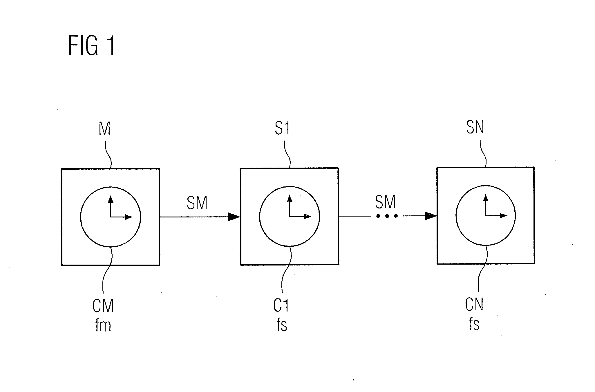
[0020]In the embodiment depicted in FIG. 1, a communication network comprises network nodes embodied, for example, as slave elements S1, . . . , SN. Each network node has a corresponding internal clock C1, . . . , CN. Each of these clocks operates at a predefined node clock frequency fs which can, in some instances, be different for different network nodes. The communication network also includes a reference node comprising, for example, a master element M, having a synchronization clock CM, which predefines a synchronization clock frequency fm, t...


PUM


Abstract

A system and method for time synchronization in a communication network. The communication network includes a plurality of network nodes each having a respective internal clock, and a reference node having a reference clock and each configured transmits synchronization messages within the communication network. At least one network node is configured to determine an estimated reference clock time discretely upon arrival of a synchronization message at the at least one network node. To that end, the at least one network node includes a controller for determining a controlled time comprising a time-continuous estimate of the discreetly estimated reference clock time. The controller is configured to determine the controlled time based on an input that is extrapolated to an execution time instant of the controller, where the execution time instant is separated from the time instant of arrival of the synchronization message by a delay (Δtdelay).

Description

BACKGROUND OF THE INVENTION[0001]1. Field of the Invention[0002]The present invention relates to data communications and, more particularly, a system and method for time synchronization in a communication network.[0003]2. Description of the Related Art[0004]Communication networks are used in a very wide range of areas to control work sequences in a decentralized manner. In particular, in industrial automation systems, it is particularly important for the automatic work processes to be coordinated with one another. This is achieved by providing the individual communicating network nodes in the communication network with internal clocks, where synchronization messages are transmitted to synchronize all the internal clocks. The internal clock of a respective network node hereby operates at a corresponding node clock frequency which may, in some instances, be different for the individual network nodes. The clocks are synchronized based on a predefined synchronization clock frequency, wh...

Claims


Application Information

Patent Timeline
Patent Type & Authority Applications(United States)
IPC IPC(8): H04J3/06
CPCH04J3/0682H04J3/0697H04J3/0664H04L7/08
Inventor OBRADOVIC, DRAGANSCHEITERER, RUXANDRASTEINDL, GUNTERWOLFRUM, PHILIPP
Owner SIEMENS AG
Why Eureka
Try Eureka