Method and device for compensating for delays of a plurality of communication channels

a communication channel and delay technology, applied in the field of data transmission technology, can solve the problems of high power consumption of serial connection circuits, limited trace, increased complexity of pcb board layout, etc., and achieve the effect of low power consumption and simple structur

Inactive Publication Date: 2008-08-28
IBM CORP
View PDF2 Cites 15 Cited by
  • Summary
  • Abstract
  • Description
  • Claims
  • Application Information

AI Technical Summary

Benefits of technology

[0008]The present invention is directed to the above technical problem, and its objective is to provide a method and device of compensating for delays of a plurality of communication channels based on standing waves, which may be applied to the communication channels of high speed parallel connection and may deal with the problem that the delay difference exceeds a clock cycle. The structure thereof is simple and the power consumption is low.

Problems solved by technology

In this way, not only the complexity of the PCB board layout is increased, but with the signal speed rising, the trace is limited due to the precision of calculation and manufacture.
However, the serial connection method also has the following problems: firstly the structure of the circuit for serial transmission is relatively complicated, and due to the existence of clock data recovery circuits, the power consumption of the serial connection circuit is very high, thereby resulting in a higher cost.
Thirdly, multiple serial connections needs a complicated mechanism for aligning the data phases between the respective serial channels, thereby resulting in a complicated initial protocol and circuit design.
Although the method declares it can reach 2.5 ps resolution in the delay network, it cannot ensure the accuracy of the phase detect circuits to reach 2.5 ps as well.
Moreover, if the delay difference exceeds a clock period, the phase cannot be detected properly with this method.
In addition, the circuit using this method is more complicated and the data transmission rate and the lengths of the transmission lines are both limited by the structure.

Method used


Image

  • Method and device for compensating for delays of a plurality of communication channels
  • Method and device for compensating for delays of a plurality of communication channels
  • Method and device for compensating for delays of a plurality of communication channels

Examples


Embodiment Construction

[0025]It is believed that the above and other objectives, features and advantages of the present invention will become more apparent through the following detailed description of the embodiments of the present invention with the accompanying drawings.

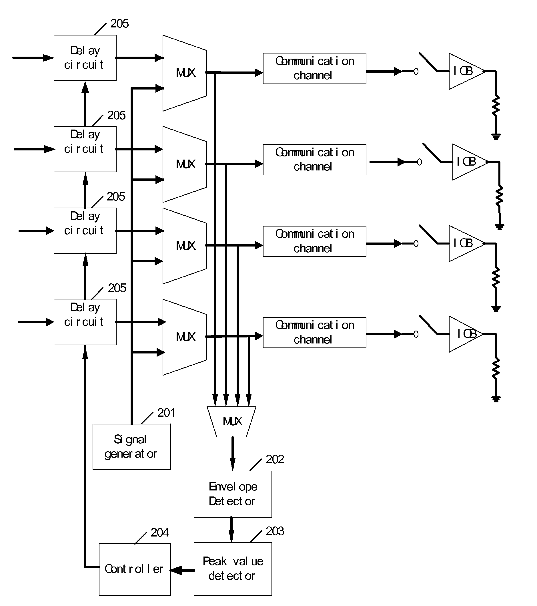
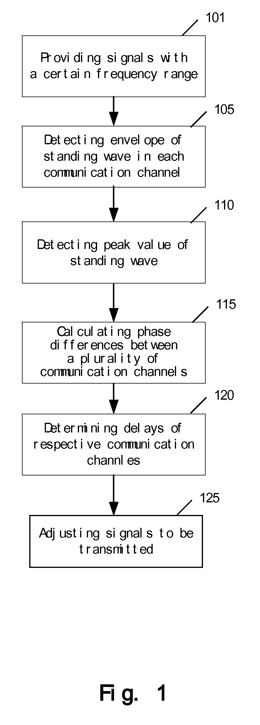
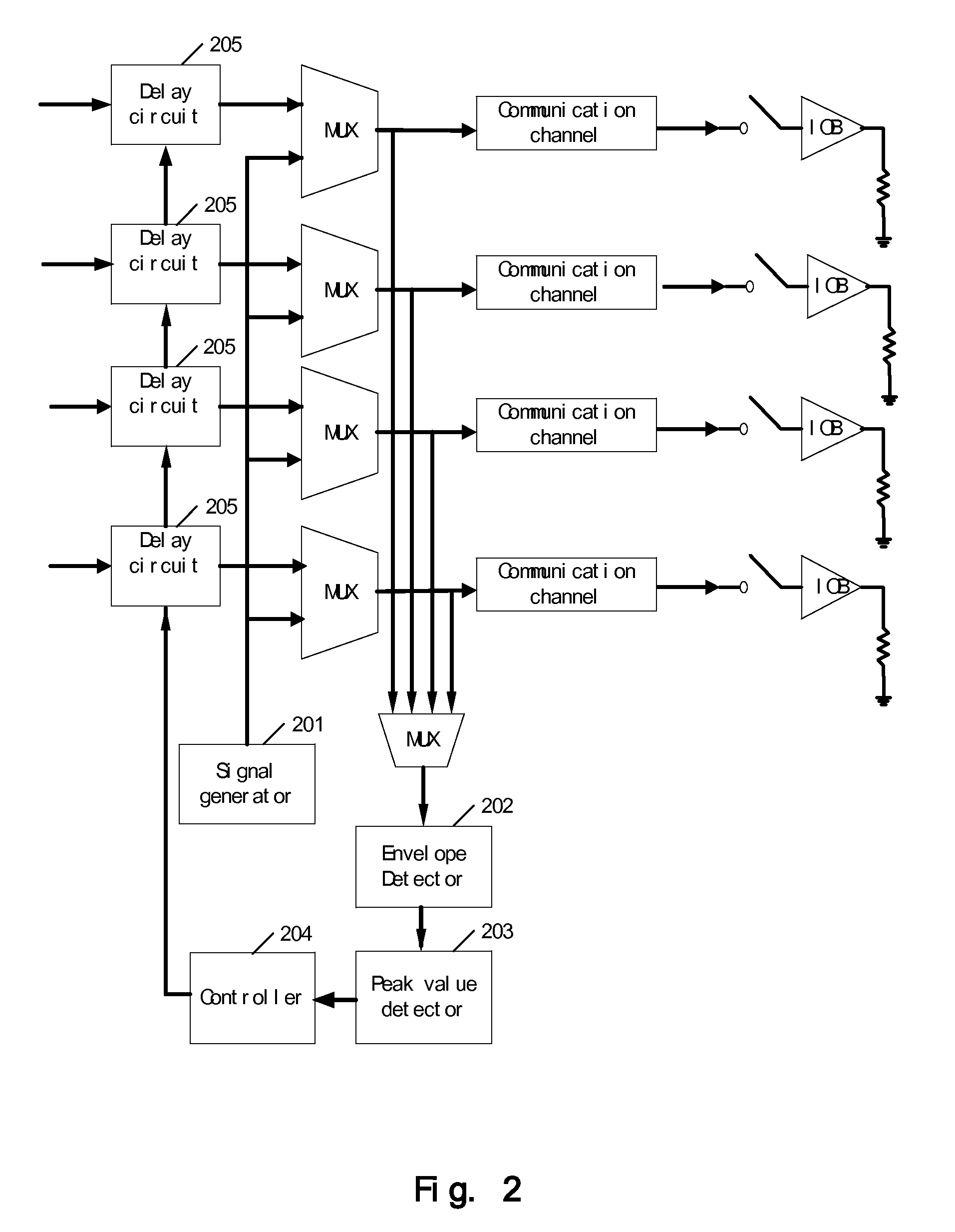
[0026]FIG. 1 is a flowchart of a method for compensating for delays of a plurality of communication channels according to an embodiment of the present invention.

[0027]According to the principle of standing wave, standing wave detection may be used for determining the lengths of transmission lines of communication channels and the corresponding transmission delays. Since the standing waves with different amplitudes are caused by the transmission lines with different lengths, the lengths of the transmission lines may be calculated and the delays of transmission lines may be determined by detecting the amplitudes of the standing waves at different frequencies, so that the transmitting signals at the transmission lines may be adjusted to re...


PUM


Abstract

A device and method for compensating for delays of a plurality of communication channels, provides signals with a certain frequency range, wherein the signals form standing waves in the plurality of communication channels; calculates phase differences between the plurality of communication channels according to the signal frequencies at the peak values of the standing waves; and determines the delay of each communication channel according to the above phase differences. The device and method may be applied to the communication channels of high speed parallel connection to eliminate the delays of the communication channels and realize length matching. Since the device and method determine the delays of communication channels by means of the phase differences, even when the delay difference exceeds a clock cycle, it can calculate the phase differences properly.

Description

TECHNICAL FIELD OF THE INVENTION[0001]The present invention relates to data transmission technology, and specifically to a method and device for measuring and compensating for delays along data transmission communication channels.BACKGROUND OF THE INVENTION[0002]For an interconnection between elements such as chips, usually transmission lines are used as communication channels for carrying data. With the increasingly development of the high-performance electronic, computing and networking apparatus, the demand for bandwidth of communication channels is being driven ever higher.[0003]A conventional method of chip interconnection is a parallel connection. In this parallel connection, the interconnection is implemented using a parallel data bus. At the transmission end, parallel data is transmitted together with a clock; while at the receiver end, the received data is sampled according to the received clock signals. As a result, the parallel connection requires that delays of all the t...

Claims


Application Information

Patent Timeline
Patent Type & Authority Applications(United States)
IPC IPC(8): H04J3/16
CPCH04L25/03878H04L25/0272
Inventor LI, YULIN, GUO HUISHEN, WEN BOYANG, YU DONG
Owner IBM CORP
Why Eureka
Try Eureka