Simple action actuator with a hydraulic fast-opening valve for controlling a clutch

Inactive Publication Date: 2006-07-27
MAGNA DRIVETRAIN
View PDF4 Cites 6 Cited by
  • Summary
  • Abstract
  • Description
  • Claims
  • Application Information

AI Technical Summary

Benefits of technology

[0009] The object is achieved in accordance with the invention, in that the self-regulating valve unit contains: a dump valve, which responds to the pressure prevailing on the side of the pump facing towards it, and a nonreturn valve between the two units, which permits a flow to take place only in the direction from the electric motor / pump unit to the cylinder / piston unit, and in that the electric motor / pump unit is reversible, as a consequence of which its supply flows in the opposite direction when in the reversed state, as a result of which opening of the dump valve is accelerated. The clutch is accordingly actuated via the control for the electric motor, which can be very rapid and accurate. The hydraulic transmission takes place via the self-regulating valve unit, which ensures that the clutch is capable of being opened rapidly without any external actuation and causes it to return to its safe (disengaged) position in the event of failure of the electrical system. This is because the valve opens if the pump pressure is completely absent. The self-regulating valve unit exhibits the dump valve for this purpose, which is acted upon only by the pressure prevailing on the side of the pump facing towards it, and not by any differential pressure.
[0011] In an advantageous embodiment, the slide of the dump valve is executed as a piston, which forms a first and a second chamber in the sleeve, of which the first chamber is capable of communicating with the cylinder / piston unit via the opening and possesses an outlet, and of which the second chamber communicates with the electric motor / pump unit. The supply of pressure medium to the cylinder / piston unit thus takes place by circumventing the dump valve via the nonreturn valve, the spring of which is appropriately dimensioned. A static pressure acts on the piston. The pressure can be maintained for a certain time in this way without the need for a follow-on supply from the pump, providing that adequate sealing is present in the cylinder / piston unit.
[0012] In a further development of the invention, the nonreturn valve is contained in the slide, for which purpose the slide exhibits at least one second opening, which is in alignment with at least the one first opening with the slide in one position, in which position the slide obstructs the communication between the first opening and the outlet. The space requirement is minimized in this way, and it is certain from the outset that the supply of pressure medium to the cylinder / piston unit will not commence until the openings for the outflow are already closed.

Problems solved by technology

Mechanisms of this kind are disadvantageous, if only because of the large number of components with their associated friction and free play.
In the case of hydraulic actuation by means of an external pump, the speed of response required for interaction with an electronic system can only be achieved with a heavily dimensioned combined electric motor and pump unit, which is out of the question for reasons of weight and, above all, power consumption.
If a pump that is dependent on the difference in the speed of rotation and rotates together with the clutch components is used instead of these, the drive must be transmitted to a rotating part, which is costly and disadvantageous.
A further problem is that, for a low difference in speed, the pressure necessary for control is not available.
In the case of rather slower operation, and with a specific torque value to be transmitted, moreover, the pressure of the pressure medium acting on the clutch must be maintained, which means high circulation losses for a non-controllable electric motor / pump unit.
As a result, the energy consumption is considerable if the pressure in the cylinder / piston unit must be maintained.
In order to permit rapid opening of the clutch, a throttled secondary circuit is required, although this makes it impossible to maintain the pressure in the cylinder / piston unit in the presence of a low supply or in the absence of any supply.

Method used


Image

  • Simple action actuator with a hydraulic fast-opening valve for controlling a clutch
  • Simple action actuator with a hydraulic fast-opening valve for controlling a clutch
  • Simple action actuator with a hydraulic fast-opening valve for controlling a clutch

Examples


Embodiment Construction

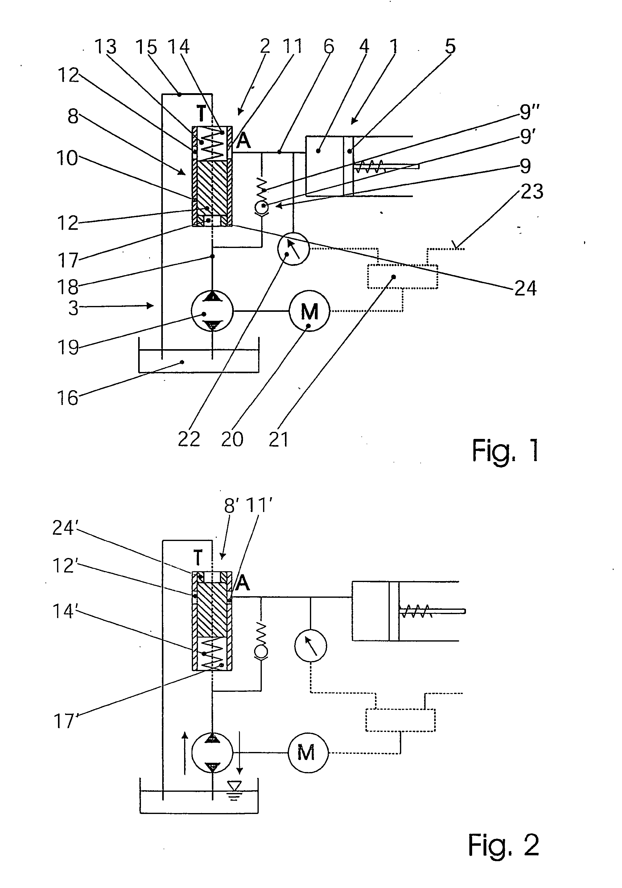
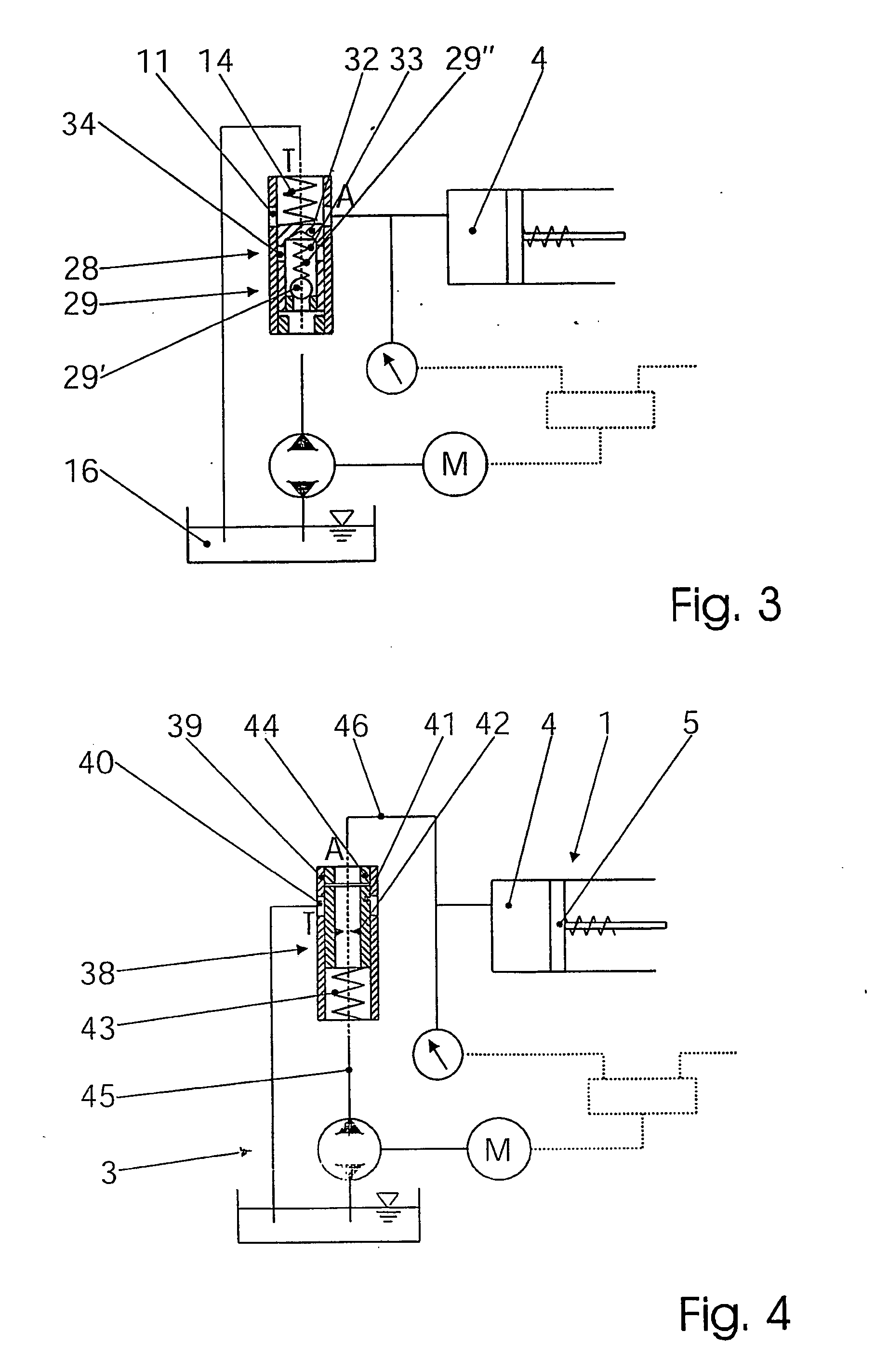
[0020] In FIG. 1, by way of summary, a cylinder / piston unit is identified with the designation 1, a valve unit with 2, and an electric motor / pump unit with 3. Provided inside the cylinder / piston unit 1 is a pressure chamber 4, which communicates via a line 6 to the valve unit 2, in conjunction with which the pressure fluid contained in the pressure chamber 4 acts upon a piston 5. This piston 5 is a part of a friction clutch (not shown here) or is permanently and directly in communication with it. The force exerted by the piston 5 against the force of a spring (not shown here) acts upon the clutch plates in the friction clutch. As the pressure increases, the torque transmitted or exerted by the clutch also increases.

[0021] The valve unit 2 contains a dump valve 8 and a nonreturn valve 9. The latter has a ball 9′ that is pressed against a seat by a spring 9″. The dump valve 8 is formed by a sleeve 10 with at least one opening 11, which opening communicates with the pressure chamber 4...


PUM


Abstract

An actuator with a simple function for the control of a friction clutch in the drive train of a motor vehicle having a cylinder / piston unit for generating the contact pressure of the clutch should be fast, inherently safe and nevertheless simple and inexpensive. For this purpose, a controllable pump (3) generates a pressure medium and makes it available to the cylinder / piston unit (1) via a self-regulating valve unit (2). A dump valve (8) consists of a sleeve (10) and a spring-assisted slide (12) therein. The sleeve has a first opening (11), through which the pressure medium can flow from the cylinder / piston unit (1). The slide (12) exposes the opening (11) in a first position and conceals the opening of a second position. The clutch is controlled in this way by actuating the electric motor.

Description

BACKGROUND OF THE INVENTION [0001] The invention relates to an actuator with a simple function for the control of a friction clutch in the drive train of a motor vehicle having a cylinder / piston unit for generating the contact pressure of the clutch, in conjunction with which a controllable electric motor / pump unit provides a pressure medium and is connected to the cylinder / piston unit via a self-regulating valve unit, so that the clutch is controlled by actuating the pump. The invention can thus relate both to clutches for locking a differential and to clutches for controlling the torque directed to an axle or to a wheel. The actuator acts in the closing direction of the clutch, and an internal force inside the clutch, such as a spring, acts in the opening direction. [0002] The requirements in respect of the controllability of friction clutches are very high for applications in a motor vehicle, both with regard to the accuracy of adjustment of a specific torque and with regard to t...

Claims


Application Information

Patent Timeline
IPC IPC(8): F16D31/02F16D48/02
CPCF16D25/14F16D48/02F16D2048/0245F16D2048/0221F16D2048/0248F16D2500/1024F16D2500/1045F16D2048/0269
Inventor QUEHENBERGER, JOHANNESGRATZER, FRANZSCHMIDL, DIETER
Owner MAGNA DRIVETRAIN
Why Eureka
Try Eureka