
Capacitive acceleration sensor arrangement

Active Publication Date: 2006-07-27
MURATA MFG CO LTD
View PDF7 Cites 9 Cited by
  • Summary
  • Abstract
  • Description
  • Claims
  • Application Information

AI Technical Summary

Benefits of technology

[0011] The object of the present invention is to provide an improved sensor arrangement, such that advantages of symmetry are achieved, and which arrangement enables reliable and effective measuring of acceleration, in particular in small capacitive acceleration sensor designs.

Problems solved by technology

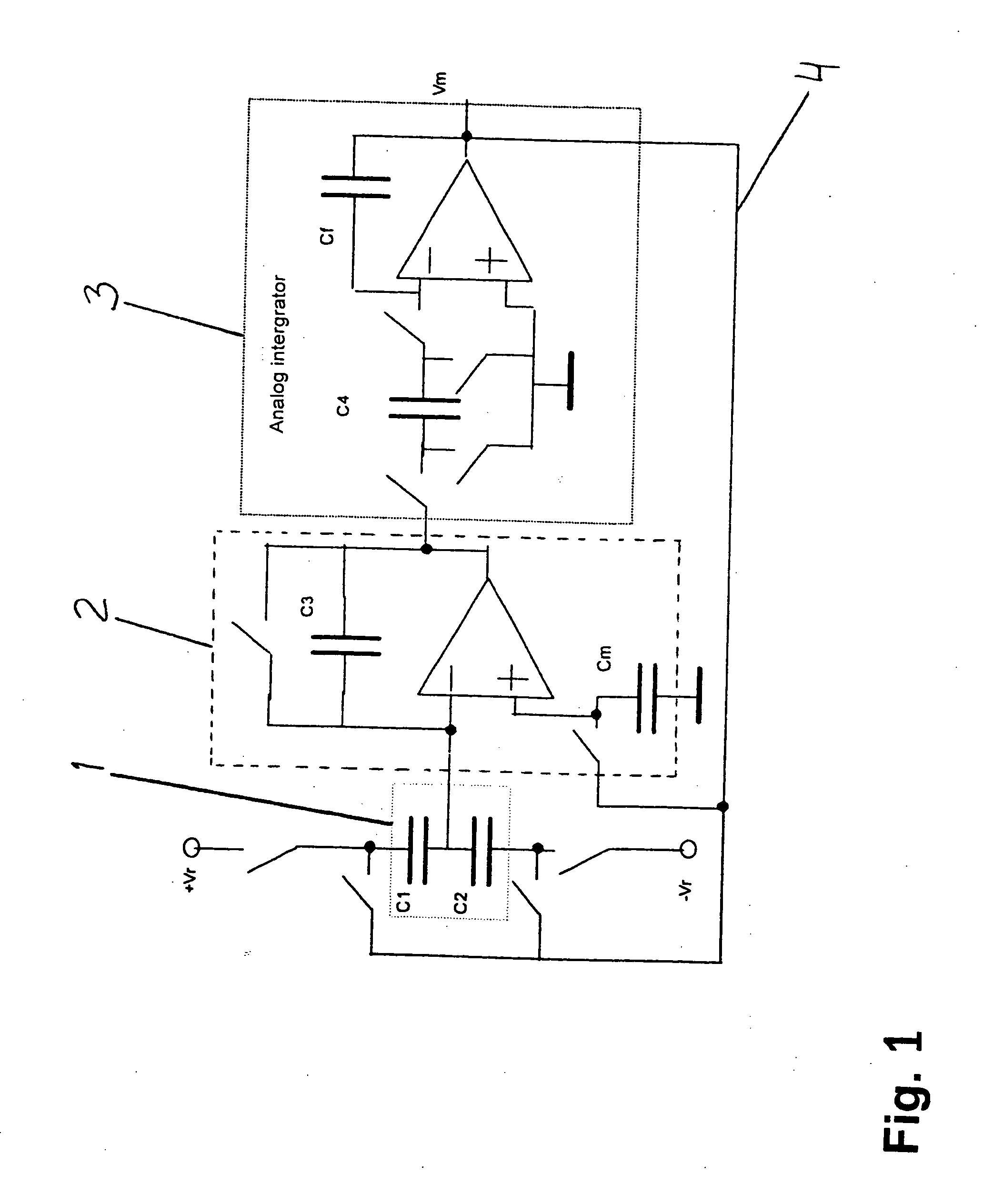
The problems in the acceleration sensor measuring circuitry according to prior art are the offset errors in the analog integrator, which always, however, affect the functioning of the circuit.
In addition, the analog integrator is sensitive to interference, in a multiplexed application, in particular.
There is also a problem in the acceleration sensor measuring circuitry according to prior art concerning the charge amplifier in a need for a large uniform range of operation because of the variation in sensor capacitances, and also, in the multiplexed case, a need for a large bandwidth, which presents a challenge for the design of the charge amplifiers and tends to increase the power consumption in the prestage.

Method used


Image

  • Capacitive acceleration sensor arrangement
  • Capacitive acceleration sensor arrangement
  • Capacitive acceleration sensor arrangement

Examples


Embodiment Construction

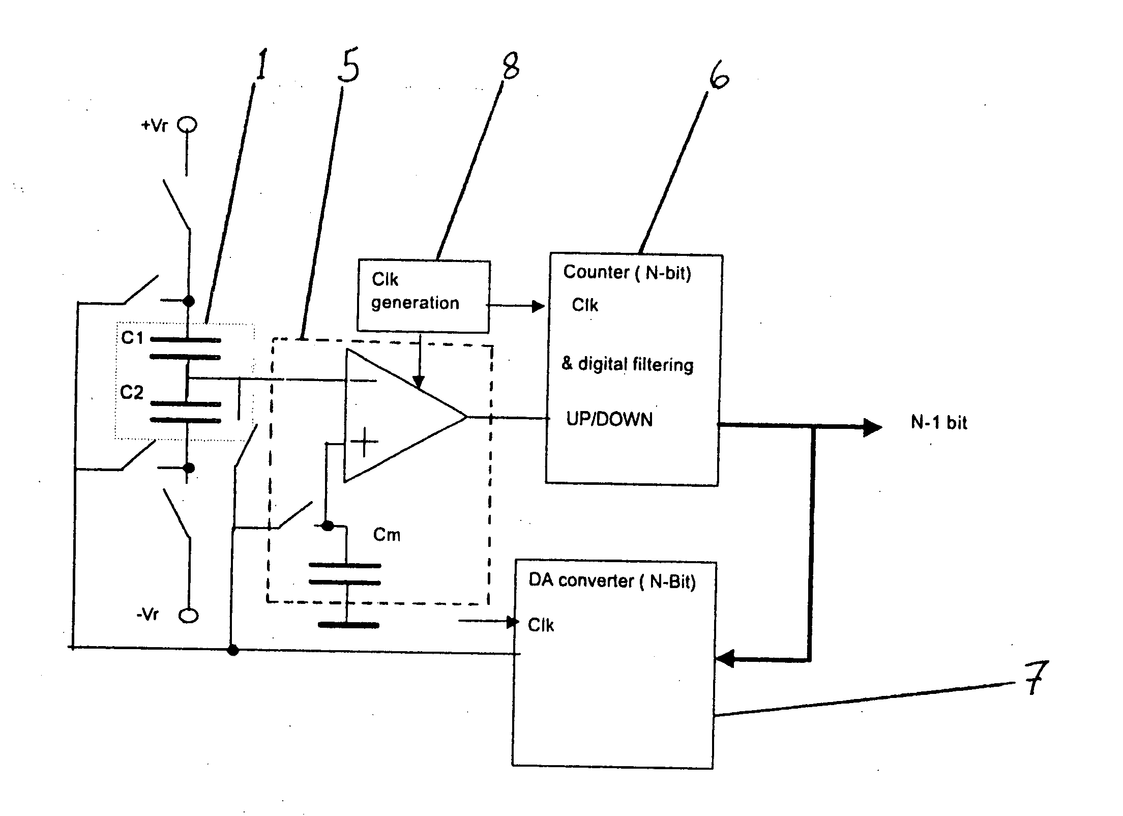
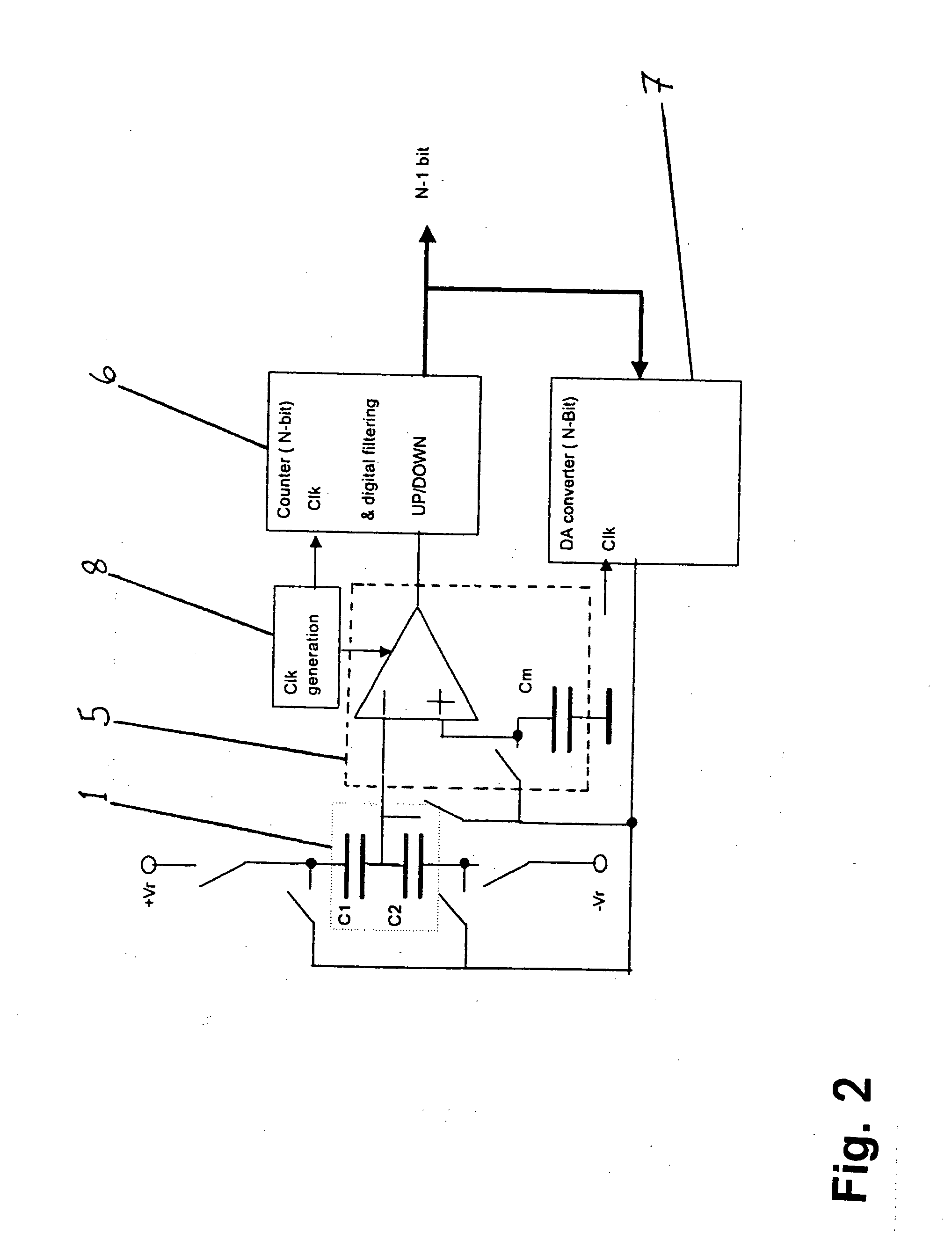
[0040]FIG. 2 shows a measuring circuitry of an acceleration sensor arrangement according to the present invention. The acceleration sensor arrangement measuring circuitry according to the present invention comprises a sensor 1 to be measured, i.e. pairs of electrodes, a digital comparator 5, a digital integrator 6, a clock signal generator 8 and a D / A converter 7 positioned in a feedback branch connection.

[0041] The digital comparator 5 in the acceleration sensor arrangement measuring circuitry according to the present invention detects the voltage difference existing between the output signal from the digital integrator 6 converted into analog form in the D / A converter 7 and the central electrode of the sensor 1, and converts the difference in potential into a corresponding digital signal.

[0042] The digital signal corresponding to the difference in potential obtained from the digital comparator 5 is added in the digital integrator 6, from which a digital output signal is received...


PUM


Abstract

The present invention relates to measuring devices used in measuring acceleration, and, more specifically, to capacitive acceleration sensors. The improved sensor arrangement of the invention enables reliable and effective measuring of acceleration, in small capacitive acceleration sensor designs, in particular. The acceleration sensor arrangement measuring circuitry of the present invention can also be applied for multi-terminal sensors, such as, for example, acceleration sensors with three axes, by using time division signal multiplexing.

Description

FIELD OF THE INVENTION [0001] The present invention relates to metering devices used in the measuring of acceleration and, more specifically, to capacitive acceleration sensors. The object of the invention is to provide an improved sensor arrangement, which enables reliable and effective measuring of acceleration, in particular in small capacitive acceleration sensor designs. BACKGROUND OF THE INVENTION [0002] Measuring based on a capacitive acceleration sensor has proved to have a simple principle and to provide a reliable method in the measuring of acceleration. The capacitive measuring is based on a change in the gap between two surfaces of a pair of electrodes of the sensor. The capacitance between the surfaces, i.e. the capacity for storing electric charge, depends on the area of the surfaces and on the distance between the surfaces. Capacitive measuring can be used already at rather low measuring ranges of acceleration. [0003] The measuring principle of the capacitive sensor e...

Claims


Application Information

Patent Timeline
IPC IPC(8): G01P15/125G01R27/26
CPCG01P15/125G01R27/2605
Inventor MANNINEN, HANNU
Owner MURATA MFG CO LTD
Learn More