
Systems and methods for controlling room air quality

a technology of air quality and system, applied in the direction of lighting and heating apparatus, heating types, separation processes, etc., can solve the problems of inability to regulate existing systems, and inability to regulate the operation of air handing, so as to minimize the speed of air moving devices and minimize the amount of fresh air introduced

Inactive Publication Date: 2006-07-27
MOHAWK VALLEY ENERGY SOLUTIONS
View PDF16 Cites 26 Cited by
  • Summary
  • Abstract
  • Description
  • Claims
  • Application Information

AI Technical Summary

Benefits of technology

[0008] Another aspect of the invention is a method for filtering at least one contaminant from air in a room, the method using an air handling system including an air moving device comprising one of a fan and a blower, the air moving device having an inlet in fluid communication with the air in the room and an outlet; a non-ionizing, polarized filtering element adapted to remove at least one contaminant from an air flow passing through the filtering element; a fresh air intake operatively connected to the inlet of the air moving device, the fresh air intake providing a fresh air flow; and an automated controller for controlling the speed of operation of the air moving device; the method including operating the air moving device to extract air from the room; passing the extracted air through the filtering element to remove at least one contaminant from the extracted air; drawing the fresh air flow into the system; returning the filtered extracted air and fresh air flow to the room; and controlling the speed of the air moving device to minimize the speed of the air moving device and minimizing the amount of fresh air flow introduced to the system.

Problems solved by technology

In addition, such prior art systems typically do not and cannot regulate the operation of the air handing to optimize the efficiency of the contaminant removal or the efficiency of the air handler.
In addition, existing systems typically are not regulated based upon the level of contamination in the internal space and are not operated to optimize the performance of the filtering medium.

Method used


Image

  • Systems and methods for controlling room air quality
  • Systems and methods for controlling room air quality
  • Systems and methods for controlling room air quality

Examples


Embodiment Construction

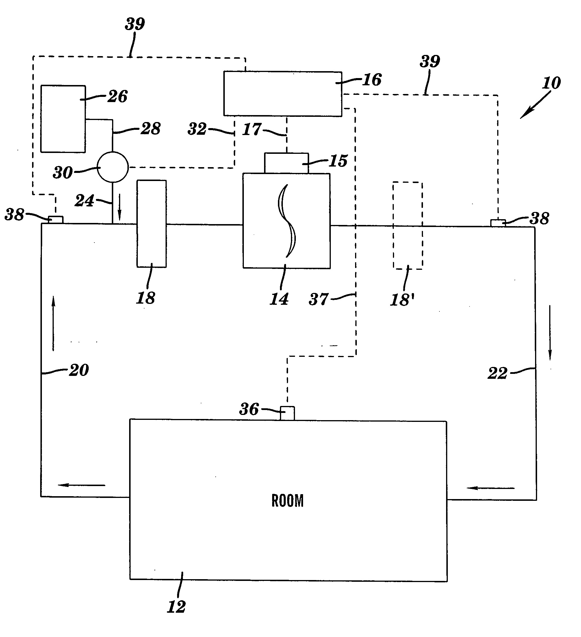
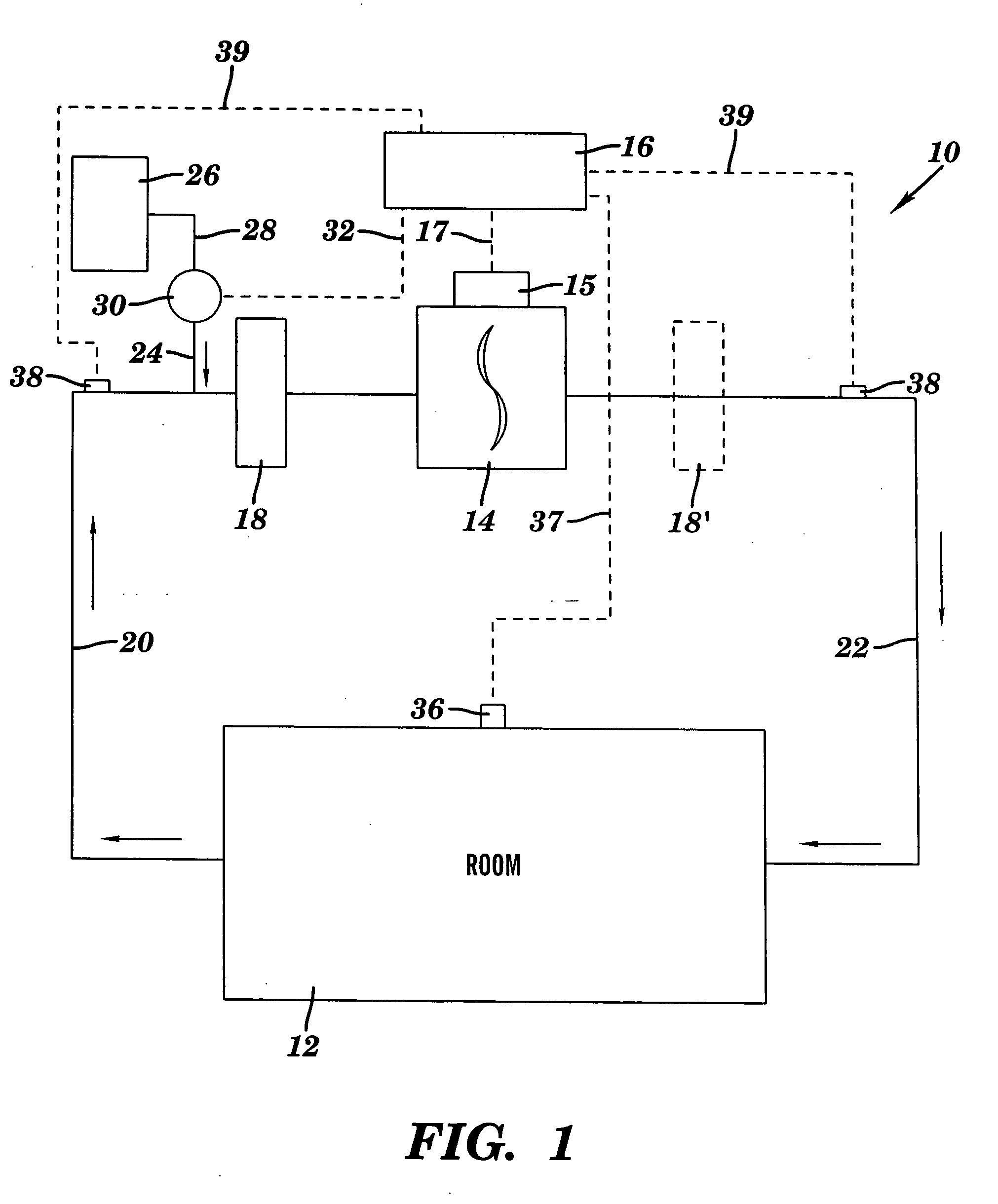
[0017]FIG. 1 is a schematic diagram of a system 10 for controlling the air quality in a room 12 according to one aspect of the present invention. Room 12 may be any internal space adapted for human habitation that may require a circulation of air, for example, for filtration, heating, or cooling. System 10 includes an air handler or air moving device 14, an air handler controller 16, one or more filtering elements 18, and appropriate conduits adapted to transfer air from room 12 to system 10. According to aspects of the invention, air handler 14 draws air from room 12 via one or more conduits 20 and returns treated air, for example, filtered air, to room 12 via one or more conduits 22. Though not shown in FIG. 1, system 10 may include a heating device or a cooling device, that is, an “air conditioner,” for heating or cooling the air passing through system 10, as appropriate. System 10 may be a system marketed under the name Energy Saving Air Cleaner™ (ESAC™) System by Mohawk Valley ...


PUM

PropertyMeasurementUnit
Fractionaaaaaaaaaa
Flow rateaaaaaaaaaa
Concentrationaaaaaaaaaa

Abstract

Systems and methods for improving the air quality of living spaces are provided. These systems and methods utilize improved filtration media and electronic control of the speed of the air handler to minimize the presence of contaminants in the air while optimizing the efficiency of the operation to the air handler. In one aspect, the speed of the air-handling device is controlled in response to the concentration of a contaminant in the living space. In another aspect, the speed of the air-handling device is controlled to optimize the filtration efficiency of the filtering medium. The systems and methods disclosed may be used in residential, commercial, and industrial settings, for example, in hotel rooms as well as for an entire home.

Description

TECHNICAL FIELD OF THE INVENTION [0001] The present invention generally relates to systems and methods for controlling the quality of air in a room. More particularly, the present invention relates to system having an air filter, an air handler, and means for controlling the speed of the air handler to optimize the air quality and minimize energy consumption. BACKGROUND OF THE INVENTION [0002] Internal air quality is an ever increasing concern for residential, commercial, and industrial buildings. The minimization or elimination of contaminants, for example, cigarette smoke, pollen, mold, and mildew, among others, is a continual concern for home owners, restaurant owners, hotel, resort, casino, office buildings, and the like is often critical to the occupants of internal spaces. [0003] Prior art systems for removing impurities from air typically include some form of filtering medium and an air handling device, such as a fan, for drawing air through or forcing air through the medium....

Claims


Application Information

Patent Timeline
IPC IPC(8): B01D46/46
CPCF24F3/166F24F11/0017F24F11/0079Y02B30/78F24F2011/0042Y02B30/746F24F2003/1635F24F11/30F24F2110/50F24F2110/40F24F11/77Y02A50/20F24F8/194F24F8/192Y02B30/70
Inventor YOST, JOHN W.IRISH, ROCCO N.
Owner MOHAWK VALLEY ENERGY SOLUTIONS
Learn More