Plastic coated metal fuel rail

Inactive Publication Date: 2006-07-27
DANA AUTOMOTIVE SYST GRP LLC
View PDF45 Cites 25 Cited by
  • Summary
  • Abstract
  • Description
  • Claims
  • Application Information

AI Technical Summary

Benefits of technology

[0008] A fuel rail in accordance with the present invention is advantageous as compared to existing fuel rails for delivering fuel to the fuel injectors for an internal combustion engine. First, a fuel rail in accordance with the present invention reduces the weight of the fuel injection system, thereby reducing the total weight of the vehicle and improving fuel economy. Second, a fuel rail in accordance with the present invention greatly reduces

Problems solved by technology

Conventional fuel rails may be made of metals, such as carbon steel or stainless steel, having a relatively high weight, thereby adding to the total weight of the vehicle with a resulting reduction in fuel economy.
Furthermore, fuel rails made of carbon steel or stainless steel may be relatively expensive to manufacture because of the use

Method used


Image

  • Plastic coated metal fuel rail
  • Plastic coated metal fuel rail
  • Plastic coated metal fuel rail

Examples


Example

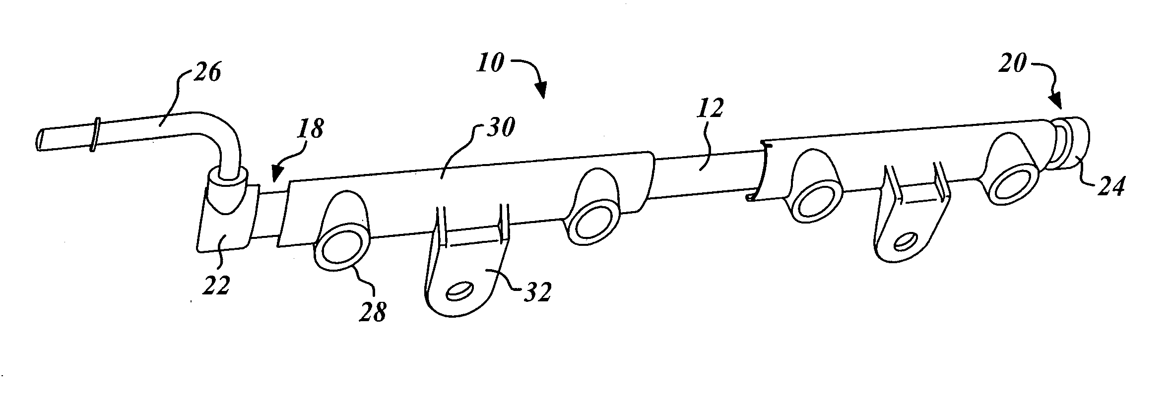
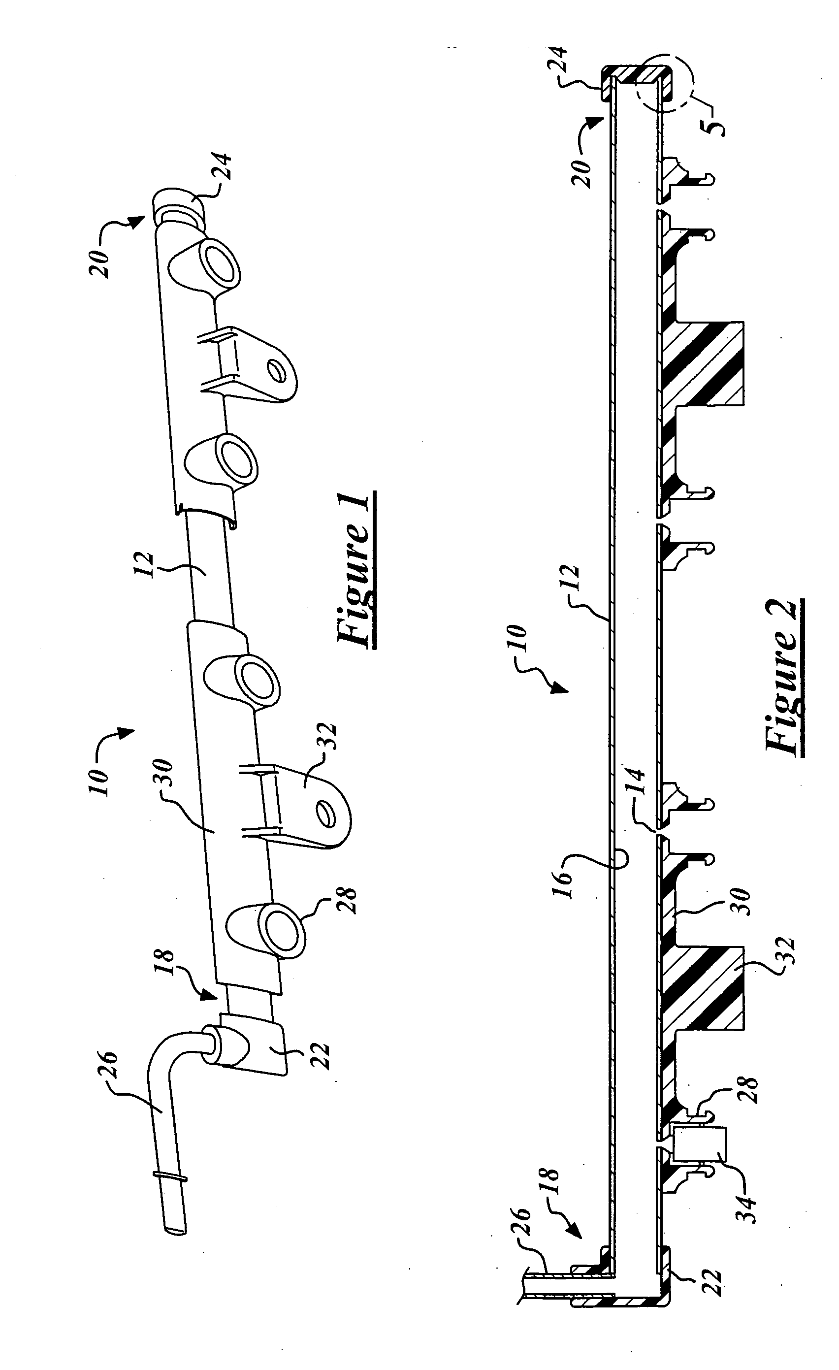
[0016] Referring now to the drawings wherein like reference numerals are used to identify identical components in the various views, FIGS. 1-2 illustrate a fuel rail 10 for delivering fuel to one or more fuel injectors for an internal combustion engine in accordance with the present invention. Fuel rail 10 is particularly adapted for use in vehicles, but may find use in other applications.

[0017] Fuel rail 10 may include a tubular body 12 defining a plurality of fuel injector ports 14 configured to receive a plurality of fuel injectors (not shown) and defining a fluid chamber 16 that serves as a fuel passageway. Tubular body 12 of fuel rail 10 may have opposite longitudinal ends 18, 20. End 18 may be open and form an inlet through which fuel enters fluid chamber 16. Accordingly, end 18 is provided for the receipt of pressurized fluid therein. Fuel is delivered to the inlet of fuel rail 12 from a fuel tank, fuel line, or other fuel reservoir components via one or more fuel supply dev...


PUM

PropertyMeasurementUnit
Weightaaaaaaaaaa
Metallic bondaaaaaaaaaa
Heataaaaaaaaaa

Abstract

An improved fuel rail for delivering fuel to a fuel injector for an internal combustion engine is provided that reduces the weight of the fuel injection system, greatly reduces manufacturing costs by eliminating expensive manufacturing methods, such as brazing, high heat welding, post plating, blow molding, and extrusion, and enhances low-cost, low-energy methods for attachment of fuel system components to the fuel rail. The improved fuel rail includes an tubular body defining a fluid chamber and having an inlet through which fuel enters the fluid chamber and a fuel injector port in fluid communication with the fluid chamber. The port is configured to receive the fuel injector. The tubular body is formed as a laminate having an inner metallic layer and an outer polymeric layer. The inner metallic layer may comprise aluminum and the outer polymeric layer may comprise nylon. Plastic or metal components can be attached to the laminated tubular body while providing a fluid tight, pressurized joint.

Description

BACKGROUND OF THE INVENTION [0001] 1. Field of the Invention [0002] The present invention relates to a fuel rail for delivering fuel to a plurality of fuel injectors for an internal combustion engine. [0003] 2. Discussion of Related Art [0004] A conventional fuel injection system includes a fuel rail having an elongated fuel passageway that distributes fuel to a plurality of fuel injectors through a plurality of fuel injector ports. The plurality of fuel injectors deliver fuel to an inlet port of a combustion chamber of an internal combustion engine. Direct fuel injection systems may include fuel injectors that inject fuel directly into the combustion chamber of the engine. Conventional fuel injection systems may further include a fuel pump that supplies pressurized fuel to the fuel rail from the fuel tank and a fuel pressure regulator that maintains the proper pressure within the fuel rail. Excess fuel may be returned to the fuel tank by a return line. In the alternative, so-called...

Claims


Application Information

Patent Timeline
IPC IPC(8): F02M55/02
CPCB29C65/3656B29C66/534F02M69/465B29C65/368B29C66/71B29C66/1122B29C66/12441B29C66/12469B29C66/72321B29L2031/7172B29K2077/00
Inventor STIELER, DAVID C.SLEEP, DALE L.
Owner DANA AUTOMOTIVE SYST GRP LLC
Why Eureka
Try Eureka